Good afternoon,
I am trying to complete components for bathroom ventilation and would like to use a CS3-1B fan timer. The fan would be 14W and as lighting would be "led" fluorescent lights.
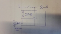
Below I show the wiring diagram for the installation. Since the resistance load of the controller for the consumer is between 20 - 350W and the fan is 14W, a resistor of min. 2,7 kΩ. I understand that it should be switched in series with the fan? Will this not interfere with the fan? Its performance? If I am thinking something wrong please comment.
 .
.
I am trying to complete components for bathroom ventilation and would like to use a CS3-1B fan timer. The fan would be 14W and as lighting would be "led" fluorescent lights.
Below I show the wiring diagram for the installation. Since the resistance load of the controller for the consumer is between 20 - 350W and the fan is 14W, a resistor of min. 2,7 kΩ. I understand that it should be switched in series with the fan? Will this not interfere with the fan? Its performance? If I am thinking something wrong please comment.
 .
.


