logo elektroda
logo elektroda
X
logo elektroda

NodeMcu V.3 vs. "bare" ESP8266-12 - launching ESPEasy

maximus22_kr 2286 7
ADVERTISEMENT
Treść została przetłumaczona polish » english Zobacz oryginalną wersję tematu
  • #1 16817698
    maximus22_kr
    Level 18  
    Hello
    I wanted to design my own board with ESP8266. First I wanted to check if on this version ( version 12 with antenna socket and antenna ).
    I connected according to the schematic below
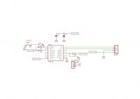
    NodeMcu V.3 vs. "bare" ESP8266-12 - launching ESPEasy .
    During programming I shorted GPIO0 to Gnd, then Reset and with ESPEasy Flasher I uploaded the file ESPEasy_v2.0.0-dev12_normal_4096,bin.

    Later I disconnected GPIO0 and reset, a new network should appear, but I wait several minutes and nothing.

    I've looked at the NodeMcu schematic and the only difference I can see is that there is no 10K resistor on GPIO2 on mine. AND that GPIO15 is shorted directly to Gnd on mine and not via a resistor. Before I start cutting GPIO15 off from Gnd ( I have it all on a board with a 2.0mm raster connector ) I wanted to ask if, according to my colleagues, this should work, or does this version of the module require a different batch ?
  • ADVERTISEMENT
  • #2 16817776
    inot
    Level 37  
    Quote:
    I have reviewed the NodeMcu schematic and the only difference I can see is that I have no 10K resistor on GPIO2. and that GPIO15 is in my case shorted directly to Gnd and not via a resistor
    .
    This does not play a role. If GPIO15 is not used as an output then you can connect directly from GND.
  • ADVERTISEMENT
  • #3 16817807
    piterek-23
    Level 33  
    maximus22_kr wrote:
    First I wanted to check that on this version ( version 12 with antenna socket and antenna ).
    .
    The ESP-12 has the antenna on the PCB and the ESP-07 has the antenna on the PCB + antenna connector.

    If you have an ESP-07 then upload the soft ESPEasy_v2.0.0-dev12_normal_1024bin
  • ADVERTISEMENT
  • #4 16817999
    maximus22_kr
    Level 18  
    Quote:
    If you have ESP-07 then upload the soft ESPEasy_v2.0.0-dev12_normal_1024bin
    .

    and this is the solution to the problem. I saw a version listing somewhere and the larger version with antenna and antenna slot had a flash of 4M

    Now I have:
    Code: Bash
    Log in, to see the code
    .

    Well it just remains to choose a GPIO that is "safe" to use. To me it seems that :
    GPIO4, GPIO5 - I2C
    GPIO2 - DS18B20
    GPIO12 - DHT22
    GPIO13, GPIO14, GPIO15, GPIO16 - buttons ( possibly MAX6675 ) , I don't know how about GPIO15

    Regarding this version with antenna on PCB, I tried to play different versions to it and I always have:
    Code: Bash
    Log in, to see the code
    .
  • ADVERTISEMENT
  • #5 16818037
    inot
    Level 37  
    GPIO15 only needs to be in the L state at reset , and then it can be used freely.
    Quote:
    When it comes to this version with the antenna on the PCB, I tried to play different versions to it and I always get:
    .
    Stack error means that these addresses do not exist.
  • #6 16818170
    maly_ninja
    Level 14  
    The schematic is correct, so this is unlikely to be the cause of the error.
    Even if the module has a 4M flash, it should work if the 1M version is uploaded, the other way round there may be some problems.

    Regarding GPIO selection, if there is a nodemcu firmware there is a note on the page:
    Quote:
    [*] D0(GPIO16) can only be used as gpio read/write. No support for open-drain/interrupt/pwm/i2c/ow.
    .
    But I don't know if it's just this firmware that has it that way, or if it's some limitation of the ESP8266 (I didn't go into it because I didn't need it).
  • #7 16818287
    maximus22_kr
    Level 18  
    Quote:
    .
    Regarding the GPIO selection, if there is a nodemcu firmware on the page there is a note like this:

    Quote:
    [*] D0(GPIO16) can only be used as gpio read/write. No support for open-drain/interrupt/pwm/i2c/ow.


    But I don't know if it's just this firmware that has it that way, or if it's some limitation of the ESP8266 (I didn't go into it because I didn't need it).


    I tested this practically, the DS18B20 thermometer did not work on this GPIO, neither did the DHT. It will serve as a possible input/output, although I intend to use the PCF8574 for this purpose ( I don't have the MCP230117, only the MCP23016 version on I2C - just that there isn't room for that many inputs/outputs in the setup - 12 max)

    Quote:
    .
    GPIO15 only needs to be in the L state at reset, after that it can be used freely.

    that's good to know, I'll put a jumper on the PCB in case I have to reset manually

    As for the ESP8266 version with the antenna on the PCB, the same error persists, I've tried uploading older versions ( e.g. R120 ) but nothing either. I only have two of these, the rest are versions with antenna and socket, so no problem, I will upload traditional soft to them.
  • #8 16818329
    inot
    Level 37  
    If GPIO15 in normal operation has an output function then even the jumper should not be directly connected to GND but via a resistor e.g. 3.3k. Otherwise a short-circuit may occur after programming (when the pin sends a high level):
ADVERTISEMENT