Elektroda.com
Elektroda.com
X

Class A headphone amplifier

liseczq 15357 129
This content has been translated flag-pl » flag-en View the original version here.
  • Hello

    I present my headphone amplifier, which, according to the author of the project, is to operate in class A.
    The amplifier consists of three blocks:

    1. Symmetrical power supply.
    2. Headphone protection / Headphone switch-on delay.
    3. Stereo power stage.

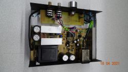
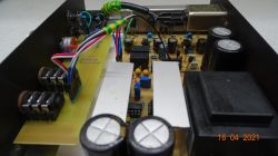
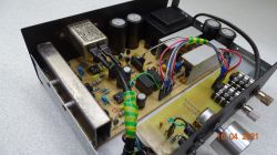
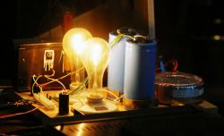
    The power supply is built around the LM723 (Motorola) chip and the LF357 fast operational amplifier. Both circuits control a pair of power transistors on which heat is deposited. Filter Capacitors: 4 X 4700uF. Power supply of the entire amplifier set to 2 X 21V PR with PR - very stable power supply. There is no difference between the magnitude of the positive and negative voltage - maybe a 10mV difference. Trafo 2 X 0.44A sealed, soldered in PCB. Everything is protected by fuses, power supply with current limitation set at 0.3A. For filtering the power supply behind the stabilizer, I used tantalum and MUSE series capacitors. I did not want to make the power supply on the LM317 and its negative counterpart. The power supply on the LM723 and the operational amplifier, which makes sure that the negative voltage follows the positive voltage, is in my opinion better.

    The protection circuit is an application of the NEC uPC1237HA chip. I started the circuit diagram with the kit from Advanced Electronic. The system delays turning on the headphones, disconnects them immediately after turning off the power, protects against DC component at the output, and protects against overload (clipping). The headphones are switched on with relays. The transistors cooperating with the circuit are low-noise. A failure / disconnection of the headphones is signaled by the LED diode. The parameters / protection time can be modified using discrete elements with the uPC1237 chip. A very good deal in my opinion.

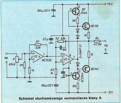
    The power stage is based on a double operational amplifier and medium power transistors. The amplifier itself is the circuit presented in Elektora 10/93 (apparently it was originally described in the Dutch ELektuur, or the German Elektor). In my amplifier I used double operational amplifiers (two stages - pre-excitation and excitation stage in one circuit) LME49860 (by default they were NE5532), while in current sources I replaced BF256 transistors with newer 2Sk170 BL group (with increased Idss current compared to GR series). The author of the power level diagram mentioned about the 50mA quiescent current. I did not manage to achieve such a current - the current in my amplifier is about 38mA per transistor when powered by 21V (by the way, the magnitude of the supply voltage does not have much influence on the change of the Idss current). The 2SK BL group trnaistors have a higher current than the original BF256A. I reduced the resistors at the gates to 47ohm. I replaced the old BAY diodes with fast 1N-4151. The amplifier in idle state heats up strongly, the total quiescent current of both channels is not all 80mA. The system works with negative feedback. A power resistor is inserted on the output, which limits the gain and additionally protects (second protection) against short-circuit at the output. There is not a single capacitor in the amplifier circuit that would limit the frequency response. The appearance of the constant component is supervised by uPC1237. Paired JFET transistors - 0.5mA Idss difference, power transistors also paired - max 5% hFE gain difference. No output offset.

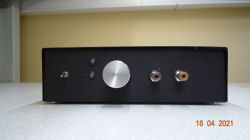
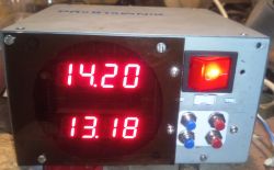
    The front panel has an ALPS potentiometer (it was supposed to be a DALLAS DS1802 digital potentiometer, but it turned out that it has a problem with transferring more amplitude), two JACK Neutrik 6.3mm sockets, two indicators - one indicating the operation of the protection, while the other signaling the power supply and the switch.

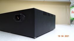
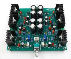
    The whole is complemented by metallized resistors - where I could I stuffed tantalum capacitors, and the company's ELNA, MUSE etc. , filter on the 230V power input (found in the cabinet, new), fuse sockets on the PCB (three in total) universal metal housing.

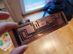
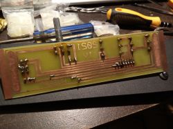
    I made the PCB in the ExpressPCB program - unfortunately, despite numerous organoleptic checks, I made a few mistakes - I had to make a few changes, bridges on the PCB during soldering. I didn't have a PCB pattern for any of the schematics - everything was designed by myself. The board is made by thermal transfer on a thick - 1mm PCB. The bottom of the plate is secured with a solution of rosin and denatured alcohol (hence a bit of dirt on the upper side of the plate). The amplifier contains quite a lot of elements and thin tracks - all connections had to be made carefully.

    I am positively surprised by the sound and sound quality of the amplifier. The amplifier sounds really beautiful. The gain is very high - you can limit it by lowering the sensitivity a bit (replacing one resistor). The whole thing took me a bit of work, but I am very happy with the amplifier. I generally tried to use good components. The stabilizer by MOTOROLA, an operational amplifier in a better class power supply, generally brand-name components.

    Advantages of the amplifier:
    - Enormous power - the amplifier will drive virtually any headphones
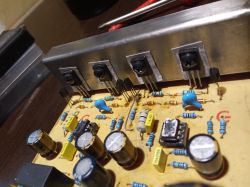
    - Very little distortion
    - Very nice sound
    - Relatively simple options for making changes: gain, sensitivity, power, bandwidth, sound.
    - Very good protection of the headphones - even in the event of burning the tips, failure of the power supply, clipping etc. the headphones will not be damaged
    - Very low amplifier noise
    - Everything is practically on one PCB

    Disadvantages:
    - Warming up of the whole
    - Pretty complicated layout
    - Lots of items

    Planned changes:
    - Replacing the potentiometer knob with one with a scale
    - Heatsink enlargement - The heat sink used in the power stage is too weak
    - Additional thermal protection of the power level

    Amplifier:
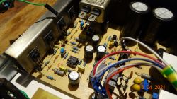
    Class A headphone amplifier

    Class A headphone amplifier

    Class A headphone amplifier

    Class A headphone amplifier

    Class A headphone amplifier

    Class A headphone amplifier

    Scheme of the power level and photos from the works:
    Class A headphone amplifier

    Class A headphone amplifier

    Class A headphone amplifier

    Class A headphone amplifier

    Cool? Ranking DIY
    About Author
    liseczq
    Level 21  
    Offline 
    liseczq wrote 849 posts with rating 156, helped 13 times. Live in city Kraków. Been with us since 2005 year.
  • #2
    conisl
    Level 11  
    Hello,

    Nice construction, well made. However, I have two comments:
    - the diagram in the output stage shows the complementary pair BD139-140, i.e. a push-pull amplifier in AB class,
    - there is a rule that in the lower position of the power switch the device is turned off, for you it is on.

    greetings
  • #3
    Fimek
    Level 15  
    Hello

    I wouldn't say that it is a class A amplifier, if you don't know what is going on inside the op-amps - they generally work in class AB. Case two - what about the damping factor? There is a series resistor in the output, which worsens the damping of oscillations from the headphone diaphragms - this seems to be a workaround for the lack of short circuit protection, but this solution is a very compromise. In my opinion, this type of amplifier is a completely unnecessarily small radiator, while it could be energy-saving and still have cosmic parameters, if only it was based on, for example, OPA-134 or another amplifier dedicated to headphones (read designed to work with a low load impedance) e.g. MAX97220A.

    I'm not picking on aesthetics, because it's OK and you can see that you've put in a lot of work - this should be praised :)

    Greetings,
    Fimek
  • #4
    popiol667
    Level 18  
    Fimek wrote:
    Case two - what about the damping factor?


    And this cannot be solved by taking the feedback signal after the resistor R4 and not before? (i.e. from the exit).

    liseczq wrote:
    The board is made by thermal transfer on a thick - 1mm PCB. The bottom of the plate is secured with a solution of rosin and denatured alcohol (hence a bit of dirt on the upper side of the plate).


    I recommend PCB varnishes - Plastik 70, Urethan spray.
    The design is very nice, what are the dimensions of the housing?

    Fimek wrote:
    I wouldn't say that it is a class A amplifier, if you don't know what is going on inside the op-amps - they generally work in class AB.

    Class A is overrated, all the advantages listed by the author could be "hooked up" to the integrated, dedicated circuit working in class D.

    An interesting experience can be trying to connect a loudspeaker to this amplifier. The volume may surprise you :)
  • #5
    mycodename47
    Level 15  
    What is the power of trafo? It looks very small ...
  • #6
    liseczq
    Level 21  
    Hello

    The transformer has 20W ... 10W per secondary winding (444 mA at over 20V per winding). Of course, if we connect a 4ohm loudspeaker, the power supply will turn out to be too weak, but this is an amplifier with parameters for headphones, not speakers (of course, it will support low-ohm headphones, but carefully with a potentiometer then).

    The 47 Ohm resistor given in the output series can be removed, even the PCB was prepared for connecting the jumper next to the resistor. This resistor is actually redundant, because uPC1237 watches over security
  • #7
    popiol667
    Level 18  
    liseczq wrote:
    The 47 Ohm resistor given in the output series can be removed, even the PCB was prepared for connecting the jumper next to the resistor. This resistor is actually redundant, because uPC1237 watches over security


    You can try to loop through the 47 ohm resistor.
  • #8
    tytka
    Level 21  
    liseczq wrote:
    I present my headphone amplifier, which, according to the author of the project, is to operate in class A.

    conisl wrote:
    this is a class AB push-pull amplifier

    Fimek wrote:
    I wouldn't say that it is a class A amplifier, if you don't know what is going on inside the op-amps - they generally work in class AB.

    I would suggest to my dear colleagues to think about what influences the class in which this amplifier works, and how it can be easily changed (because you can easily maneuver between class A and AB). :)

    This project seems to be years ago, it was published in "Radioelektronik".

    popiol667 wrote:
    Class A is overrated, all the advantages listed by the author could be "hooked up" to the integrated, dedicated circuit working in class D.

    In my opinion, class D for headphones is more of a joke (unless on the phone).

    liseczq wrote:
    The author of the power level diagram mentioned about the 50mA quiescent current. I did not manage to achieve such a current - the current in my amplifier is about 38mA per transistor when powered by 21V (by the way, the magnitude of the supply voltage does not have much influence on the change of the Idss current).

    liseczq wrote:
    When idle, the amplifier heats up a lot, the total quiescent current is a little over 150mA.

    So how about this quiescent current?
    38mA per channel, and a total of just over 150mA? How many channels does this amplifier have?
    The quiescent current is due to the current sources on the Jfets that you changed and that's probably the reason you didn't get a higher value.
    The supply voltage does not affect the quiescent current because you have current sources.
  • #9
    Fimek
    Level 15  
    E there, it seems to me that the D class can also sound well with headphones. However, there is a question why to do it - class D amplifiers have advantages in the form of high efficiency, say independent of the drive and low output impedance even in open loop, but they also have disadvantages. In an amplifier with mains supply, the advantages do not matter, but the disadvantages remain.

    However, upon reflection, I give my colleague the title right - the output current of either of the two operational amplifiers does not change (the first has practically no load, and the second works with a current source, i.e. high impedance), therefore it is indeed, even formally, class A.

    I have absolutely no conviction to the sense of class A. Maybe someone will enlighten me why use it nowadays?

    Greetings,
    Fimek
  • #10
    popiol667
    Level 18  
    popiol667 wrote:
    In my opinion, class D for headphones is more of a joke (unless on the phone).


    In order to compare the systems, we use parameters, not feelings.
  • #11
    liseczq
    Level 21  
    liseczq wrote:
    The author of the power level diagram mentioned about the 50mA quiescent current. I did not manage to achieve such a current - the current in my amplifier is about 38mA per transistor when powered by 21V (by the way, the magnitude of the supply voltage does not have much influence on the change of the Idss current).


    It says in the topic that 38mA for one transistor, i.e. for the entire power amplifier (both channels), not all 80mA of quiescent current.
    2SK170BL have a higher current than the BF256A mentioned in the radiolectronics ...
  • #12
    M. S.
    Level 34  
    Quote:
    38mA per transistor


    Only that the same current also flows through the second transistor, so it cannot be said that a current twice as large flows together. As for the class of the amplifier, it is rather class AB, but the quiescent current is quite large in relation to the output current, so the power amplifier can work quite linearly.
  • #13
    liseczq
    Level 21  
    Yes - quiescent current per channel 38mA, let's round - 40mA quiescent current per channel. In my opinion, the amplifier sounds very well, the whole thing heats up very much
  • #14
    kris8888
    Level 36  
    What about temperature stabilization? Shouldn't these JFETs or serial diodes be somehow mounted on the heat sink together with the power transistors? At the moment, the only stabilization is provided by these ten ohm emitter resistors, the question is whether it is enough.

    Is the quiescent current stable and does not change when the transistors warm up?

    As for the aesthetics of workmanship, it is at a high level, but I just don't like the wraps made of yellow-green tape. Tights would be better. I would also change the input jack to two, standard cinch, somehow it suits me better as an input.
  • #15
    Janusz_kk
    Level 36  
    liseczq wrote:
    the whole thing gets very hot

    Therefore, I would change the resistors in the sources of these fets from 100 to 200 or even to 300.
  • #16
    User removed account
    Level 1  
  • #17
    kris8888
    Level 36  
    acctr wrote:

    kris8888 wrote:
    Is the quiescent current stable and does not change when the transistors warm up?

    Sure it changes, but is it important when the system works in a negative feedback loop?

    Well, I don't see any temperature feedback here. But since the final transistors do not go up with smoke after some time, it means that the current eventually stops at some value and still does not increase by itself.
    Perhaps the temperature characteristics of the pn junctions of the diodes used in series between the bases of the transistors already provide sufficient temperature stabilization.
    Anyway, the transistors will not go up in smoke since the power supply has a current limit of 0.3A
  • #18
    User removed account
    Level 1  
  • #19
    romarcin
    Level 17  
    Fimek wrote:
    There is a series resistor at the output, which worsens the damping of oscillations from the headphone diaphragms

    there is a German standard DIN50332 (now European so EN) for the measurement conditions of headphones, which assumes that the headphones are powered from a signal source with a resistance of 120 Ohm! keyhole" :wink: in the amplifier, and there the signal is formed from resistor voltage divider !, apart from what "damping" here, the headphone diaphragm is some milligrams, these are not woofers!
  • #20
    Janusz_kk
    Level 36  
    acctr wrote:
    Either class A or cool transistors, you can't have both.

    but the author complains that:
    liseczq wrote:
    the whole thing gets very hot

    So you have to decide whether this heating bothers him or not.

    acctr wrote:
    Reducing this current will reduce the quiescent current in the emitter circuit and shift operation towards class B.

    But they still work in AB, depending on the quiescent current, only the 'depth' of this class changes.

    acctr wrote:
    And what would it do? In the circuit from the original diagram, a current of about 2.25mA flows through the source resistors.

    Not much, but then the drop on the diodes will decrease and the power amplifier will have a lower quiescent current, you can also put a potentiometer between the BD bases and reduce the quiescent current, which is simply too high for the headphone amp.
  • #21
    liseczq
    Level 21  
    Janusz_kk wrote:
    liseczq wrote:
    the whole thing gets very hot

    Therefore, I would change the resistors in the sources of these fets from 100 to 200 or even to 300.


    Hello

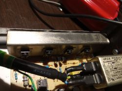
    Increasing the resistor will reduce the quiescent current of the tip. The heating does not bother me - I'll add a little more cooling. So far, such a piece of sheet metal connected to the casing is hot after 15 minutes (the upper casing is pulled down, if it is on, it would probably fry) - it burns the pad (I note that I work a little physically) after a dozen or so seconds - you do not have to play hard in inches - it is now empty hot.

    Radiator:

    Class A headphone amplifier

    By default, the system was to include transistors: BF256A. BF256 transistors are grouped according to the Idss current. By default, the author used the BF256A in the system - they have a spread of 3 - 7 mA. This is the group with the least Idss

    I used 2SK170 from the BL group (they are grouped: GR, BL, V). BL is the middle group - 6-12mA dispersion. Mine are paired and have ~ 10mA (+/- 0.5mA). In addition, I reduced the resistor to 47ohm (100ohm by default) which should increase the current. I managed to reach ~ 40mA per channel. The current does not diverge - now my amplifier is hot and I have 780mV on emitter resistors. 780mV / 20ohm = 39mA.

    The amplifier played for a long time (up to two hours) and nothing got burnt. I note that the whole is powered by 42V (symmetrical 2 X 21V).
  • #22
    tytka
    Level 21  
    liseczq wrote:
    that is, for the entire power amplifier (both channels), not all 80mA of quiescent current.

    And yet. So where did the previous over 150 mA come from?

    liseczq wrote:
    the whole thing gets very hot

    You indicated the reason here:
    liseczq wrote:
    I note that the whole is powered by 42V (symmetrical 2 X 21V).


    In the project from the magazine, the amplifier is powered with a voltage of +/- 15V, i.e. with a quiescent current of 40 mA, the heat sink heating goes to 1.2 W per channel, you supplied this system with a voltage of +/- 21V, so you heat the heat sinks with a power of 1.68 W per channel .
    The amplitude of the output signal when powering the headphones does not reach such a large value that a higher supply voltage is needed. By increasing this voltage, you only made a bigger heater out of this device.

    popiol667 wrote:
    In order to compare the systems, we use parameters, not feelings.


    On a preliminary comparison, yes, yes. However, to choose an amplifier that suits me sonically; however, I prefer it additionally
    your listening experience. Unfortunately, the parameters alone do not say everything about the sound.

    I was intrigued by the author's words:
    liseczq wrote:
    it was supposed to be a DALLAS DS1802 digital potentiometer, but it turned out that it has a problem with transferring higher amplitude

    Could you please write something more about it.
    This headphone amplifier has enough amplification to fully drive it with a signal not exceeding +/- 2 Vpp (exaggeratedly), and the mentioned DS should probably be able to handle such levels perfectly. Maybe something else was wrong, or you had a damaged chip?
  • #23
    dktr
    Level 23  
    I use a headphone amplifier with 4 ? loudspeakers and I am very pleased with the results, it can play quite loud and when I take a pause there is no noise - even if I put my ear to the tweeter.

    Class A headphone amplifier
  • #24
    popiol667
    Level 18  
    tytka wrote:
    popiol667 wrote:
    In order to compare the systems, we use parameters, not feelings.


    On a preliminary comparison, yes, yes. However, to choose an amplifier that suits me sonically; however, I prefer it additionally
    your listening experience. Unfortunately, the parameters alone do not say everything about the sound.


    Of course, the auditory sensations are influenced, for example, by the awareness that we are listening to an amplifier that, in our opinion, works in the best class, e.g. A and not D.

    On the other hand, the fact that you hear the difference in the sound of the two amplifiers shows that either of them (or both) are kicked. The parameters of amplifiers have long gone far beyond human perception. All these nuances, minor differences between devices disappear in a blind A / B / X test.
  • #25
    Fimek
    Level 15  
    popiol667 wrote:

    Of course, the auditory sensations are influenced, for example, by the awareness that we are listening to an amplifier that, in our opinion, works in the best class, e.g. A and not D.

    On the other hand, the fact that you hear the difference in the sound of the two amplifiers shows that either of them (or both) are kicked. The parameters of amplifiers have long gone far beyond human perception. All these nuances, minor differences between devices disappear in a blind A / B / X test.


    I would like to read the convincing arguments that Colleague popiol667 is wrong :) however, it is obvious that I share this opinion.

    Greetings,
    Fimek
  • #26
    kris8888
    Level 36  
    M. S. wrote:
    As for the class of the amplifier, it is rather class AB, but the quiescent current is quite large in relation to the output current, so the power amplifier can work quite linearly.

    It should be checked what is the operating point and the flow angle of the output transistors. But with such a small amplitude of the output voltage, low power and high quiescent current, this amplifier can actually work in pure class A, only in a push-pull configuration.
  • #27
    liseczq
    Level 21  
    tytka wrote:
    liseczq wrote:
    that is, for the entire power amplifier (both channels), not all 80mA of quiescent current.

    And yet. So where did the previous over 150 mA come from?

    liseczq wrote:
    the whole thing gets very hot

    You indicated the reason here:
    liseczq wrote:
    I note that the whole is powered by 42V (symmetrical 2 X 21V).


    In the project from the magazine, the amplifier is powered with a voltage of +/- 15V, i.e. with a quiescent current of 40 mA, the heat sink heating goes to 1.2 W per channel, you supplied this system with a voltage of +/- 21V, so you heat the heat sinks with a power of 1.68 W per channel .
    The amplitude of the output signal when powering the headphones does not reach such a large value that a higher supply voltage is needed. By increasing this voltage, you only made a bigger heater out of this device.

    popiol667 wrote:
    In order to compare the systems, we use parameters, not feelings.


    On a preliminary comparison, yes, yes. However, to choose an amplifier that suits me sonically; however, I prefer it additionally
    your listening experience. Unfortunately, the parameters alone do not say everything about the sound.

    I was intrigued by the author's words:
    liseczq wrote:
    it was supposed to be a DALLAS DS1802 digital potentiometer, but it turned out that it has a problem with transferring higher amplitude

    Could you please write something more about it.
    This headphone amplifier has enough amplification to fully drive it with a signal not exceeding +/- 2 Vpp (exaggeratedly), and the mentioned DS should probably be able to handle such levels perfectly. Maybe something else was wrong, or you had a damaged chip?


    Hello - I misled you. Total quiescent current is ~ 80mA ( no 150mA - my mistake ).

    Dallas DS1802 is powered by 5V (symmetrical +/- 2.5V). Feeding a signal (eg from a sound card with an amplitude greater than the supply voltage caused clipping of the signal - distortion. Moreover, MUTE was not able to suppress large amplitudes.

    Amplifier acc. sounds very nice to me - it drives high-impedance headphones without any problems. The author of the power amplifier swears that it is class A . I improved its parameters a bit by inserting 2Sk170 (everything is paired as for the gains). I have no way to prove to you the quality of the sound. I have an oscilloscope and I can make some measurements in my free time. I have already enlarged the radiator for it, I am planning a few more aesthetic changes.
  • #28
    popiol667
    Level 18  
    liseczq wrote:
    Amplifier acc. sounds very nice to me - it drives high-impedance headphones without any problems. The author of the power amplifier swears that it is class A. I improved its parameters a bit by inserting 2Sk170 (everything is paired as far as the gains are concerned). I have no way to prove to you the quality of the sound. I have an oscilloscope and I can make some measurements in my free time. I have already enlarged the radiator for it, I am planning a few more aesthetic changes.


    A class AB amplifier up to a certain signal amplitude is a class A amplifier.

    After all, nobody tells you to prove the quality of the sound. When looking at the build quality I take my word for it :)

    I am looking at a diagram of a similar design (simplified, resistors instead of FET). 1W power on 8ohm load, frequency response 10-30kHz (-3dB). The headphones have a huge reserve of power and amplitude at the output. It has no right to play badly, whether in class A or AB. You can try a switch that reduces the quiescent current and see if you can hear a difference in the sound (even better ask someone to switch it so that you don't know what the amplifier is in).

    Congratulations on the refined design.
  • #29
    tytka
    Level 21  
    liseczq wrote:
    Amplifier acc. sounds very nice to me - it drives high-impedance headphones without any problems. The author of the power amplifier swears that it is class A


    You don't have to prove it to me how it plays. I've made some similar constructions so I know.
    With the quiescent current you give, I think with at least 200mW output, you are class A.
    I would only suggest that you think about reducing the supply voltage, because such a high voltage is not needed here, and only as I mentioned, it leads to an increase in the power lost to heat sinks.

    liseczq wrote:
    Dallas DS1802 is powered by 5V (symmetrical +/- 2.5V). Feeding a signal (eg from a sound card with an amplitude greater than the supply voltage caused clipping of the signal - distortion. Moreover, MUTE was not able to suppress large amplitudes.

    What kind of sound card do you have that you get this signal level? Does it have an additional amplifier?
    You could possibly do an input divider before DS.

    Fimek wrote:
    I have absolutely no conviction to the sense of class A.

    Likewise, some are not convinced by diesel engines, while others praise them.
    Fortunately, there are several classes of amplifiers and everyone can choose something for themselves. And I am not going to convince anyone of any of them.

    popiol667 wrote:
    On the other hand, the fact that you hear the difference in the sound of the two amplifiers shows that either of them (or both) are kicked. The parameters of amplifiers have long gone far beyond human perception.

    So, for example, listening rooms in good salons offering audio equipment are only there to check which amplifier with parameters beyond human perception is factory-kicked. Or so?
  • #30
    popiol667
    Level 18  
    tytka wrote:
    Likewise, some are not convinced by diesel engines, while others praise them.


    You gave a very good example - the fact that someone is not convinced about diesel will in no way affect the real parameters of this engine.

    tytka wrote:
    So, for example, listening rooms in good salons offering audio equipment are only there to check which amplifier with parameters beyond human perception is factory-kicked. Or so?


    It is primarily used to sell a product. The idea is for you to leave as much of your money as possible in this salon. I rather doubt that it is blindly A / B / X tested under conditions where the user does not know which hardware is working. Blind A / B / X tests do not go hand in hand with large sales of, for example, expensive audio cables.

    Fimek wrote:
    I would like to read the convincing arguments that Colleague popiol667 is wrong :) however, it is obvious that I share this opinion.


    Colleague, give better convincing arguments, preferably the results of a well-designed A / B / X test.

    Who knows, why not win the $ 1 million James Randie Prize?