logo elektroda
logo elektroda
X
logo elektroda

Once again - Small headphone amplifier - ty.ytka

tytka 3360 16
ADVERTISEMENT
Treść została przetłumaczona polish » english Zobacz oryginalną wersję tematu
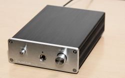
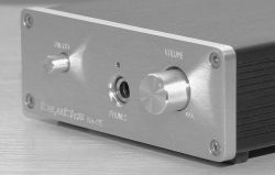
  • Close-up of the front panel of a headphone amplifier with on/off switch, headphone jack, and volume knob. .

    The design of this headphone amplifier, is actually an update of my earlier design presented here ( Link ).
    Compared to the original version, a few things have been changed. The one that is immediately apparent is the casing.
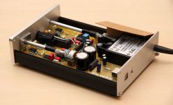
    The new housing is slightly larger. Its internal dimensions are: 105 x 160 x 35mm (with external: 115 x 168 x 40mm). The dimensions of the amplifier board are: 97 x 159.5mm. So, there is now slightly more space. The board itself is now not pushed into the profile, but fixed to the underside of the case, via spacers 5mm high. From the side edge of the plate to the side wall, there is 4mm of space on each side. The area of the housing that is adjacent to the mains voltage area of the PCB has been shielded with 0.5mm thick pre-shrink. The mains cable exit from the enclosure, is sheathed in a dedicated rubber bend.


    All the work involved in machining the raw case to adapt it for this project was done by myself.
    The lettering was engraved, using a small, simple CNC machine.
    Just to pre-empt any questions, I would like to inform you that this time the engraving was not filled with paint on purpose. The idea was for the description to be there, but relatively subtle.

    Now perhaps a little about the electronics.
    For those who haven't seen the previous version, let me remind you that this is a design based on Douglas Self's project on achieving higher power when connecting operational amplifiers in parallel.
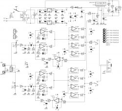
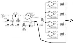
    Compared to the previous version, the circuit has been slightly simplified. The amplifier section has been shortened to two stages. Why? The previous version was actually a fitting for a power amplifier realised on operational amplifiers, which I was working on at the time ( Link ). It was known that the circuit there (power amplifiers) would need more gain. However, in a headphone amplifier, such an elaborate circuit is not needed. So I decided to simplify it, resulting in only two stages remaining. The first is a parallel voltage amplifier (2 operational amplifiers) and the second is also parallel, but this time a current amplifier (4 operational amplifiers).
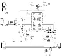
    The rest of the circuitry, i.e. the power supply, the protection circuit, and the DAC, remained as before.
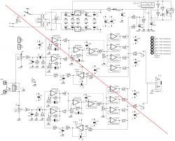
    Headphone amplifier schematic with NE5532N and TL072 components. .
    Electrical schematic of a headphone amplifier with parallel operational amplifiers. Block diagram of a headphone amplifier circuit based on PCM2705. .
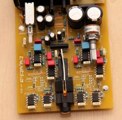
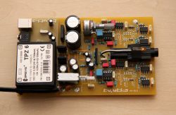
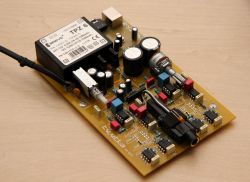
    Close-up of a headphone amplifier circuit board with electronic components. Printed circuit board of a headphone amplifier with various electronic components. Circuit board of a headphone amplifier with electronic components. .

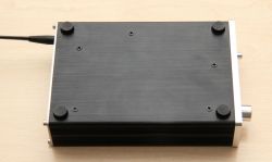
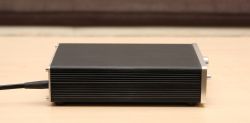
    Below are a few more photos showing the end result.
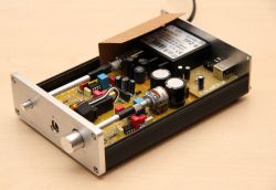
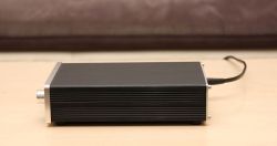
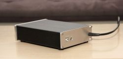
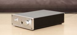
    Open headphone amplifier with visible PCB and electronic components in an aluminum case. Headphone amplifier in a new larger case with a mounted electronic board. Bottom view of a headphone amplifier with a new, larger enclosure. Black headphone amplifier with a visible power cord, placed on a table. Black headphone amplifier with a visible power cord, placed on a table. Black headphone amplifier with a new, larger case on a wooden table. Upgraded headphone amplifier with larger casing. Metal enclosure of a headphone amplifier with a volume knob and headphone jack. Headphone amplifier in a metal case with front buttons. Headphone amplifier in a metal case with front buttons. .

    However, I will take the liberty of posting the results of the amplifier measurements, as these will also be there, at a later date.

    And one additional piece of information.
    The previous enclosures have not gone to waste. They were used for other devices, which quite possibly will be presented here..

    Cool? Ranking DIY
    About Author
    tytka
    Level 22  
    Offline 
    tytka wrote 677 posts with rating 1739, helped 8 times. Live in city Pabianice. Been with us since 2006 year.
  • ADVERTISEMENT
  • #2 21297746
    Piottr242
    Level 23  
    Each time, I am impressed by the aesthetics and refinement of the design.
    What is a U3 circuit in an oblong housing? The output protection?
    And a second question - do you mill the front panel in-house or do you have someone where such can be ordered?
  • #3 21297815
    Anonymous
    Level 1  
  • #4 21297943
    wiorekw
    Level 15  
    Another very nice design, I'm very curious to see the measurements and how they compare to the previous, heavily developed version, how much the performance has deteriorated (or improved?).
  • ADVERTISEMENT
  • #5 21298062
    _Avalanche_
    Level 7  
    You, when you throw something in, it's always a masterstroke, your designs are top notch :)
  • #6 21298350
    pikarel
    Level 38  
    It is a pleasure to look at each of your projects, the attention to detail of workmanship is exemplary in DiY.
    You have improved the design by what you deemed worthy of correction.
    Obviously a big plus from me.

    I'm not a gadgeteer by nature and always attach headphones to the jack on the unit.
    Your amplifier would be complete for me if it included an RIAA EQ circuit, enabling me to listen directly to real analogue recordings from the 'asphalts' of the era, without a heap of other 'blocks'.
    Please don't take this as a criticism, it's just a loose, non-committal comment.
  • #7 21298724
    Bucefal76
    Level 17  
    You are already approaching the level at which I would spend the money to buy. A little more refinement to the lettering on the front panel and we have a commercial level of workmanship.
  • #8 21298845
    katakrowa
    Level 23  
    I see the paper under 230V is :-) .
  • #9 21299448
    saly
    Level 32  
    I'm impressed with the design and aesthetics. It looks great and probably works just as well.


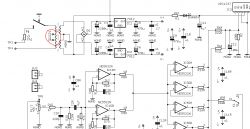
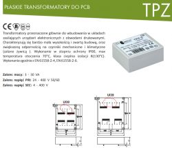
    I noticed a little zonk in the schematic but that's probably a Czech error.

    A section of an electronic schematic showing circuits and components.

    Diagram and description of flat transformers for PCB with device illustration.
  • ADVERTISEMENT
  • #10 21299511
    gulson
    System Administrator
    Something wonderful. There is no denying that some users are waiting for the ty.tyk presentations with baked goods!
    I guess you haven't received the goodie kits from Elektroda yet, send a Parcel Post, it will be a pleasure.
  • #11 21299568
    Anonymous
    Level 1  
  • ADVERTISEMENT
  • #12 21300397
    tytka
    Level 22  
    Thank you very much for your comments.

    Of course, I'm aware that the level of my projects is still not up to par with the commercial ones, but for the time being, that's all I can afford.
    And also considering the workshop I have (or actually don't have), the end result, gives me some moderate satisfaction.

    And referring to your posts:

    - "What is the U3 circuit ?" It is a protection circuit. It delays the switching on of the headphones, and automatically disconnects them if any DC voltage is present at the output.

    - "Do you mill the front panel yourself ?" Yes I did the machining myself. Only the lettering was milled. The holes were made with a table drill and refined with a mini grinder.

    - "Two parallel amplifiers in the first stage ?" Apparently not necessary in this case, although they have their advantages. But note that the board is the same as in the original version, so there was no other option.

    - "An operational amplifier in a 'global feedback' loop?" Well, it's well known that DC-servo circuits probably have as many opponents as supporters. I am, let's say, in the middle, but in this project I decided to use it.

    - " A 6R8 resistor at the output?" Maybe its value seems high. I used it to protect the outputs of the circuits in case of a possible short circuit of the amplifier output. And to be honest, I personally don't use low impedance headphones. Of the ones I own, the least is 44 ohms.

    - " likewise the resistors on the output of the secondaries" I there, would not dare to give up those 1 ohm resistors.

    - "The amp would be complete for me if it included an RIAA equalization circuit" Very interesting and inspiring comment. I won't change it anymore in this amp, but I am thinking of upgrading, my tube OTL. I will strongly take this under consideration.

    - "The paper under 230V is" In the previous version there was a foil, but supposedly wrong, not enough etc.

    - "I noticed a little zonk in the schematic". This is a result of the fact that I had a transformer of the same dimensions in the library, but without the split primary winding. And at the moment, it was quicker to do such a myopic than to add a new component to the library.


    I promised to post the measurement results of this amplifier.
    There will be some curiosity here, you will see how the PCM2705 chip, turns out to be quite a bottleneck in terms of the measurement results obtained.

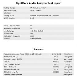
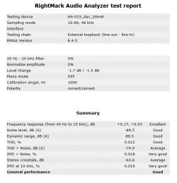
    Here is a report of measurements of the amplifier driven from the line input:

    Screenshot of a RightMark Audio Analyzer test report for device HA-015_line_50mW. .

    And this report, is the result of a test carried out, when driven from the digital input:

    Screenshot of a sound test report from RightMark Audio Analyzer program. .

    It appears that I have not achieved the parameters declared in the PCM2705 note :( .
  • #13 21301611
    wiorekw
    Level 15  
    If I'm not mistaken, this simplified version has slightly better performance than the previous, more elaborate version, especially the THD, which is almost halved. I'm already overlooking the fact that this is probably beyond the limit of perception in either case.
  • #14 21301658
    katakrowa
    Level 23  
    tytka wrote:
    It appears that I have not achieved the parameters claimed in the PCM2705 note
    .

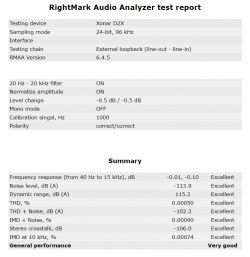
    Interesting... You must have something wrong. I would expect a lot more from analogue too.
    Can you give measurements of the card/interface itself?
  • #15 21302333
    tytka
    Level 22  
    In fact, this version came out slightly better in the tests carried out. But this may be partly due to the slightly changed measuring conditions.

    It doesn't look like anything is wrong.
    It's just that the PCM2705 surprisingly comes out poorly in the tests I ran. I also tested it on another device.
    Maybe I'll give it another go.

    And if you want to see the card's measurement, here you go:
    RightMark Audio Analyzer test report for Xonar D2X device. .
  • #16 21304213
    siewcu
    Level 35  
    Where did you get this enclosure from? I ordered some from the net, it was supposed to have these dimensions, it arrives and here's the trick, the dimensions are given for the outside and it's not possible to put the board inside. This would have been ideal.
  • #17 21305458
    tytka
    Level 22  
    wiorekw wrote:
    If I'm not mistaken, this simplified version has slightly better performance than the previous one
    .

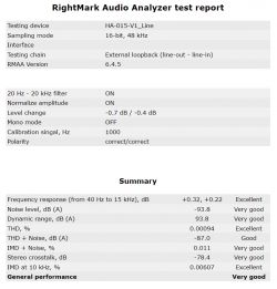
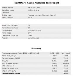
    Today I had a moment, so I tested the original/more elaborate version (as it sits in a drawer one without a case) under the same conditions as now this revised, or simplified, one.
    For the line input:

    RightMark Audio Analyzer test report for HA-015-V1_Line device showing measurement results. .

    For USB input:

    Screenshot of a RightMark Audio Analyzer test report for the HA-015-V1_dac device. .

    Unfortunately I am not able to achieve better results in measurements with this PCM.
    The situation is similar with my other battery-powered headphone amplifier ( Link ).
    There I accidentally achieve virtually identical performance.

    siewcu wrote:
    And where did the colleague get this enclosure from?
    .

    And from Alie...
    I bought a few months earlier, but now I checked and the auction is still active. So if you want it, get back to me on priv and I'll provide you with a link.

Topic summary

The discussion revolves around an updated design of a headphone amplifier, featuring a larger casing and improved internal layout. Key modifications include a new housing design, enhanced shielding for the mains voltage area, and a protection circuit (U3) that delays headphone activation and disconnects them in case of DC voltage presence. Users express admiration for the aesthetics and craftsmanship, while also questioning certain design choices, such as the use of dual amplifiers in the first stage and the operational amplifier's feedback loop. Measurements indicate that the revised version performs slightly better than the previous model, although some users suggest further simplifications for improved performance. The author confirms the machining of the front panel and shares insights on the testing conditions and results.
Summary generated by the language model.
ADVERTISEMENT