Elektroda.com
Elektroda.com
X
This content has been translated flag-pl » flag-en View the original version here.
  • #31
    dktr
    Level 23  
    Compile it under Arduino 1.6.7
  • #32
    george2002

    Level 21  
    dktr wrote:
    Compile it under Arduino 1.6.7


    This is a problem in Windows XP, I worked on the topic, just type in google Windows xp arduino esp8266 bits

    Info e.g. Here
  • #33
    po_48
    Level 9  
    thanks helped
    now i have a problem with the file
    es-rs485_v2.ino
    Arduino: 1.6.7 (Windows XP), Tile: "Generic ESP8266 Module, 80 MHz, ck, 26 MHz, 40MHz, QIO, 8M (7M SPIFFS), 2, v2 Lower Memory, Serial, None, Only Sketch, 115200"

    Project options changed, reload all
    D: \ a \ ESP \ es-rs485_v2 \ es-rs485_v2 \ es-rs485_v2.ino: In function 'void setup ()':

    es-rs485_v2: 19: error:'earchwifi 'was not declared in this scope

    searchwifi ();

    ^

    exit status 1
    'nazwawifi' was not declared in this scope

    in the file
    WiFiUartTransparentBridge.ino
    compilation runs smoothly
  • #34
    dktr
    Level 23  
    You mixed up something in the code. I downloaded pik again and it compiles without any problems.

    The sketch uses 238,477 bytes (54%) of program memory. The maximum is 434,160 bytes.
    Global variables use 32,532 bytes of (39%) dynamic memory, leaving 49,388 bytes for local variables. The maximum is 81,920 bytes.
  • #35
    po_48
    Level 9  
    I downloaded all the es-rs485_v2.ino files
    what are they in the subject and I have the same in all of them
    unless the arduino-1.6.7 version does not suit him
  • #36
    Janusz_kk
    Level 37  
    po_48 wrote:
    bits / os_defines.h: No such file or directory

    You're missing this file.
  • #38
    po_48
    Level 9  
    why I have these errors
    Arduino: 1.8.5 (Windows XP), Tile: "Generic ESP8266 Module, 80 MHz, ck, 26 MHz, 40MHz, QIO, 1M (64K SPIFFS), 2, v2 Lower Memory, Disabled, None, Only Sketch, 9600"

    Project options changed, reload all
    Archiving built core (caching) in C: \ DOCUME ~ 1 \ admin \ SET ~ 1 \ Temp \ arduino_cache_730353 \ core \ core_esp8266_esp8266_generic_CpuFrequency_80, ResetMethod_ck, CrystalFreq_26, FlashFreq_40, FlashMode_qio, FlashSize_1M64, LED_2, LwIPVariant_v2mss536, Debug_Disabled, DebugLevel_None ____, FlashErase_none, UploadSpeed_9600_6ab5e78c2376f2c1663435181e2f3eb0 .and
    The sketch uses 250,248 bytes (26%) of program memory. The maximum is 958,448 bytes.
    Global variables use 32,656 bytes (39%) of dynamic memory, leaving 49,264 bytes for local variables. The maximum is 81,920 bytes.
    warning: espcomm_sync failed
    error: espcomm_open failed
    error: espcomm_upload_mem failed
    error: espcomm_upload_mem failed
  • #39
    dktr
    Level 23  
    COM port visible in the system? selected this port in ArduinoIDE? If the port is present, is there any activity when trying to program? (led RX / TX)? The 3.3V from this programmer on some boards has too low current efficiency, what do you power it with?
  • #40
    po_48
    Level 9  
    port visible LEDs are flashing
    3.3v power supply given separately

    Added after 4 [minutes]:

    in ESPlorer, communication is two-way and in ArduinoIDE as if only one stone

    Added after 23 [minutes]:

    in ArduinoIDE I am sending in the serial port monitor I am sending node.info () and I do not receive a response
    reaction to physical reset
    NodeMCU 0.9.6 build 20150406 powered by Lua 5.1.4
    lua: cannot open init.lua
  • #41
    dktr
    Level 23  
    It looks like you would not connect GPIO0 to ground before programming and ESP is still lua and not soft from the thread.
  • #42
    po_48
    Level 9  
    it seemed to me that the gpi00 short circuit is used for flashing

    Added after 14 [minutes]:

    and this is where the dog was buried, but these are the mistakes of someone who starts playing with andruino, thanks for the help
  • #43
    SpiderPL
    Level 2  
    uzi18 wrote:
    george2002 wrote:
    Is it something like esp-link? https://hackaday.io/page/1304-virtual-serial-port-tunnel-to-use-with-esp-link " target="_blank" rel="nofollow noopener ugc" class="postlink inline" title="" > https://hackaday.io/page/1304-virtual-serial-port-tunnel-to-use-with-esp-link because esp-link has a lot of options, only the RS485 support is probably not implemented from what I read quickly :)
    How about stability? and it works at what speeds and whether they can be changed easily or the code needs to be uploaded to esp8266 to make it different :) ?


    There is an esp-link latka with rs485 support, you have to look at repo / issue
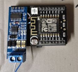
    Unfortunately, I did not manage to make this version work ...
    However, it worked from https://github.com/pvvx/esp8266web
  • #44
    scaevola
    Level 10  
    I know I'm digging up an old thread, but I'm looking for information to control.
    I am trying to make a link from the pro-vent recuperator to domoticz on the basis of your program, but somehow it does not work for me. First of all, I don't know how to master the device addressing.
    Is your link transparent to the device? This would mean that I have to give an address on domoticzu. How is the end of the bus terminated?
    Second, when I tried to connect to the driver in parallel, the driver kept crashing errors. I have a manual for a recuperator and the addresses are described there - but I must admit that I do not understand rs485 too much.
    I use a converter like yours.
  • #45
    levy^
    Level 17  
    You must bear in mind that RS485 is a topology / type of network when it comes to equipment, and what you put on it, e.g. modbus, is a completely different pair of wellies.
  • #46
    scaevola
    Level 10  
    Yes, I know that rs485 is a hardware protocol and modbus is software.
  • #47
    levy^
    Level 17  
    write to PW then maybe I can help, let's not clutter this thread, just describe exactly what equipment you have
  • #48
    ACCel
    Level 22  
    Using a different adapter (in the picture) you can use any software that supports the TTL serial port.
    TCP-IP / RS485 ESP8266 converter
    I used ESP-Easy.
    The author of the thread wrote the software itself, but I preferred to use the ready one with the web panel and other features.
    But I did not find an ESP software that would support the DE pin used for RS485 transmission signaling (because it is half-duplex).
    Therefore, you need to buy an adapter that is not the usual MAX3485, and additionally converts serial full-duplex transmission to half-duplex.

    You can also connect any additional sensors to esp-easy as you need.

    levy^ wrote:
    modbus is a completely different pair of wellies

    https://www.elektroda.pl/rtvforum/viewtopic.php?p=19386913#19386913

    Here is perhaps the easiest way to program modbus in python.
  • #49
    Karol966
    Level 31  
    dktr wrote:
    ESP8266 programmed in ArduinoIDE

    What libraries should be included to compile it? I don't use arduino at all so forgive the question. It is about:
    Quote:
    fatal error: ESP8266WiFi.h: No such file or directory
    Probably the next library will also not be known #include
    P.S. Once I tried to run anything on these wifi modules and I downloaded a lot of different libraries, when I entered the name of this file in the add-ons, despite the installation of several libraries from the list, I still have the same problem. I'm using Arduino IDE 2.00 on windows 7 and it's very unstable... so maybe that's the problem?

    P.S. I'm pretty green when it comes to wifi etc. I'd like to connect my air handling unit (airpack home4) to the network first. What next, once I start this converter and connect the control panel to it (I'm going to plug into the same wire that goes to the Air++ panel, after all it's a modbus sort of ... )
  • #50
    dktr
    Level 23  
    First you need to add the URL to the board manager in the preferences, then you need to add the ESP8266 in the board manager and then select such a "board" from the menu tools -> board
  • #51
    Karol966
    Level 31  
    I skipped Arduino IDE, compiled your program with VSC+PlatformIO and uploaded to NODE MCU V3. In the terminal I got to "going to UART mode BRIDGE10.10.10.89" :) What's next ? Is this bridge 2 sided? Can I send something to the ESP8266 / its uart and read the same, from where, a browser or maybe some ready-made program on a PC?
    For now, I have not connected anything to the NodeMCU board, at the beginning I would like to connect it via FTDI FT232 to another port on the computer and test the communication strictly.
  • #52
    dktr
    Level 23  
    Yes, it is two-sided, under linux you can use socat, under windows I don't know, there is probably some equivalent ;)