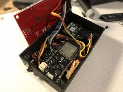
Thermal imagers have been fascinating for years. The idea that you can watch images in a part of the spectrum of electromagnetic radiation, inaccessible to our eyes on a daily basis, is extremely interesting and appealing. Unfortunately, the implementation of this task is not cheap - especially if we want to buy this type of camera only to play with it, and not use it in some specific commercial applications in which it could earn a living.
The author of the project below wanted to enter the world of thermography, but without having to pay a large price for the device. So what more could he do, if not just to build this type of camera himself. This task is not easy, but it is also not impossible to implement. Below you will find a description of the individual components of this type of device and information on how they were connected to each other.
sensor
The first stage in the construction of the camera was to choose a sensor. The choice in this project fell on the microbolometer.
The sensor is a key element of every camera. It is also the most expensive and the most difficult element to buy. Some distributors, such as Digi-Key, offer infrared sensors, but they are usually too expensive or simply not available.
A good and inexpensive source of sensors are damaged devices, especially miniature thermal imaging cameras that work with smartphones such as FLIR One and Seek Thermal Compact.
The author managed to purchase a damaged second generation FLIR One camera. It only cost him 75 pounds. Damage: "The camera does not turn on", which usually indicates a power or battery failure. Usually in such damaged systems the sensor itself works correctly.
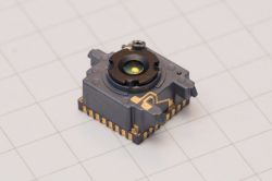
The camera uses a FLIR Lepton 3 sensor with a resolution of 160x120 pixels:
For this price it would be hard to buy anything else. These cameras (from the second generation) are no longer available, and FLIR One Pro of the third generation costs about 400 pounds.
The author, as soon as the package with a damaged camera came, began to disassemble the sensor. For an additional 25 pounds, he purchased a FLIR Lepton sensor mounting plate. The use of this type of plate significantly facilitates further work with this sensor.
After mounting the sensor on the board, the author connected everything to the Raspberry Pi to check the operation. Controlling Lepton 3 is very simple, just use its dedicated software, contained in the pylepton library, which can be found on Github. After starting the application, it turned out that the sensor is working properly, which means that you can go on to work on a DIY thermal imaging camera.
Hardware
The author of the project wanted to build an independent and portable device, so he had to add a display and battery to the sensor, and of course some processor. The camera communicates via the SPI interface, so it was easy to write drivers using spidev and a module for streaming data directly to a web client in JavaScript, however this type of solution is not suitable for a small battery-powered system.
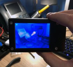
The choice of screen was quite simpler. The ILI Technology company from China offers a wide range of inexpensive TFT displays with a built-in controller. These screens are often used in hobby projects and have extensive support in the environment. The author chose a compact 2.8 "display with an ILI9341 controller. These types of screens are most often sold together with extensive development boards, with integrated touch screen controllers, SD card slots, etc. The screens themselves, however, can be purchased online.
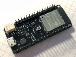
To control the entire device, the author chose the well-known ESP32 chip from Espressif. This platform offers a fantastic ecosystem, especially thanks to the integration of Wi-Fi and Bluetooth interfaces in one module. In addition, which is very important in this project, this system has two SPI hardware interfaces that will be needed to control the thermal imaging sensor and TFT display.
In order not to have to independently integrate this system with the rest of electronics, the author used the WEMOS LOLIN32 module. This module also has an integrated charger for lithium-ion batteries on board. All necessary system pins are conveniently led out to the pin connectors on the board.
The author has added a simple switch to the module - all sensor and display power supply control is done with ESP32 via PNP transistors. Thanks to this, after switching off the system it is still possible to charge the built-in battery.
Software
Creating firmware for the built camera was not difficult at all. The author used the FLIR Lepton 3 camera driver he created, which he tested under Linux. Porting firmware on ESP32 turned out to be very simple - basically it was enough to replace the spidev library API with the one that ESP32 offers for its SPI interfaces.
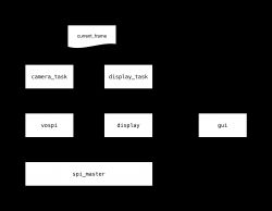
The entire application on ESP32 works under the care of the FreeRTOS real-time system, which divides individual system operation elements into tasks. One task uses VoSPI (Video over SPI) to rip images from the sensor, and the other task displays the collected frame through the second SPI interface on the system screen.
The current - validated as correctly collected - picture frame (current_frame) is a shared variable between two tasks, access to which is controlled by the semaphore. Due to the fact that the screen resolution is exactly twice the image from the sensor, there was no need for complex scaling of data from this variable.
The camera_task task collects frames from the sensor using the VoSPI protocol created by FLIR. This task also deals with resynchronization of the video stream, which may be needed and updates the current_frame variable only if the collected frame is assessed as correct.
The display_task task, in turn, deals with the display of data from the current_frame variable. They are saved as four quadrants of the image, as recorded by VoSPI. It is quite a convenient solution, therefore the author has not decided to introduce an additional step that converts such a picture frame to another format, containing e.g. a full picture frame.
Before any of the image segments is displayed on the screen to the voice, there is a subsystem creating a user interface that adds the appropriate notes, text and simple shapes to the image, which are saved in a separate list. Currently, the interface is not very extensive, because it is basically in the testing phase. The user_task task deals with the operation of the graphical interface and the only thing it currently does is change the visibility of the simple green square visible in the upper left corner. It just blinks every second.
The only difficulty resulting from the division of the image into quarters is the fact that when drawing a GUI the system must be aware of which quadrant is currently, especially if we want to draw an element - e.g. a rectangle - that extends to more than one quadrant. These kinds of problems make GUI implementation a little difficult, which explains why the author does not yet fully use its capabilities.
Housing
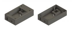
The author decided on a 3D printing enclosure, as he recently joined the owners of this type of printer (Prusa i3 MK2S). 3D printing is great fun, so it's good to use its capabilities to create a case for your own device.
The casing was supposed to be small and contain all elements of the system - display, battery, module with ESP32 and of course the thermal imaging sensor. The author began designing the housing by collecting the sizes of all elements from the data available on the network and measuring the remaining elements with a caliper, if the dimension was not available in the documentation.
The housing has been designed in Autodesk Fusion 360.
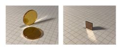
One of the challenges when creating the housing was to properly protect the camera against dirt and damage. Unfortunately, the glass is not suitable for such applications - it does not pass enough infrared from the part of the electromagnetic spectrum that interests us. Therefore, you had to look for better material for the camera window. The industry typically uses one of two materials - germanium and zinc selenide.
Initial tests were carried out with a window made of zinc selenide, unfortunately the results were far from satisfactory. It turned out that despite covering the windows with anti-reflective layers, the window reflected a lot of infrared generated by the camera itself to the sensor.
Finally, the author used a Germanium window, which was installed in the FLIR camera, from which the sensor was previously downloaded. This window is a bit small (8 mm x 8 mm), but certainly optically much better than the window with ZnSe, which was tested first.
Before the final housing was created, the author produced several test copies. Only the third version of the project turned out to be a match. 3D printing tolerance is a difficult matter, keep this in mind when designing any elements. After assembling all the elements (which was done without squeezing a few things by force), the author managed to close the housing and get a compact DIY camera. As the author himself admits, the next version of the enclosure will probably be slightly larger, especially since Fusion 360 calculates all interference quite poorly and does not allow a realistic estimate of how tight the enclosure can be.
In the housing, the author used M2 screws to mount the module with the sensor and the plate with ESP32 to the housing. The Germanium window in place has been secured with a bit of kapton tape so as not to damage it - this is a much more delicate method than gluing it to the housing.
From the outside, M3 Allen screws secure the display on one of the walls. The display frame, unfortunately, has not been equipped with appropriate clips, which means that it does not lie evenly along the entire perimeter of the screen, but thanks to the holes for M3 screw heads, the whole looks nice and elegant.
The housing allows the use of the micro-USB socket built into the module with ESP32 to charge and upload new software to the module.
Summary
The finished camera works quite well. The camera firmware is still being developed. The system has a lithium-polymer cell with a capacity of 1300 mAh, which ensures a long time of operation of the system between charges. When all systems are turned off and put to sleep, ESP32 only charges 250 microamps from the cell. When the camera and display are turned on, the power consumption increases to approximately 230 mA.
The next step in the system development is connecting to the camera's I?C interface to be able to use functions such as field of view correction (FFC) or display other telemetry data from the sensor itself, such as information about its temperature.
The author's next plans concern the use of the touch panel on the screen to control the system. Unfortunately, it is also connected to SPI, so it will have to share one of the interfaces - with a camera or screen. Currently, you need to first check what will have a smaller impact on the smooth operation of the camera, after all, we do not want the touch screen to slow down the image refresh on the display.
Source: https://damow.net/building-a-thermal-camera/
Cool? Ranking DIY


