logo elektroda
logo elektroda
X
logo elektroda

Ford / Mondeo / MK3 Speedometer - CAN - I need data about the meter pinout

kordian2 13833 16
ADVERTISEMENT
Treść została przetłumaczona polish » english Zobacz oryginalną wersję tematu
  • #1 17012155
    kordian2
    Level 10  
    In order to learn the CAN bus, I bought two counters "in advance":

    1 - Form Mondeo MK3
    2 - Hyundai Coupe

    At the time of purchase, I was not very familiar with the whole subject of CAN. Sometimes I just act ahead of time and put myself in front of a problem to be solved ... and solve those problems somehow :)
    This was the case with websocket, esp32 .. etc.

    The counter number two from the Hyundai Coupe after opening it did not show me all the electronics and I could not get to the bottom side, so I opened the MK3 counter. Here the faceplate with the indicators has slightly detached.

    I tracked the 70006TB chip, i.e. the CAN converter. After analyzing the PCB, I was able to determine its pinout for power and CAN pins.
    After connecting 12V, I checked the supply voltage of the CAN system, which was 5V.
    Unfortunately, I do not know the purpose of the rest of the pins.
    Applying only 12V does not start the meter (nothing is lit) and the system consumes practically no electricity.
    I suppose that one of the pins must wake up the counter or as a colleague from the forum suggests

    "Modern counters work in such a way that the processor takes a few microamps during sleep mode. It wakes up only after receiving the appropriate frame on the CAN bus, not by any pin like 20 years ago."

    At the moment I have an MCP2515 controller connected to the Atmega 2560, ELM327, an oscilloscope and I can generate the desired frame to wake up the counter.

    Unfortunately I do not know what form this frame is a Generating possible combinations for everyone is probably not a good idea.

    Maybe some of my colleagues have some information that could help me wake up the meter and maybe they have CAN commands that control its peripherals?

    Thank you very much for help.
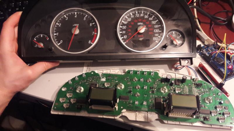

    Ford / Mondeo / MK3 Speedometer - CAN - I need data about the meter pinout


    Ford / Mondeo / MK3 Speedometer - CAN - I need data about the meter pinout
  • ADVERTISEMENT
  • #2 17027542
    żałosna udręka
    Level 34  
    Simply the voltage on CAN does not wake up?
  • #3 17031168
    ste
    Level 28  
    This counter (Mondeo MK3) does not wake up CAN. You need to enter the second plus, the so-called "after ignition", which in the car goes from the ignition (terminal 15), pin No. 2 in the meter.
  • #4 17031226
    Samuraj
    Level 35  
    When it comes to the counter for 508 and 3008, the matter is completely different here. The appropriate data frame activates the counter. Without this frame, which is fed in periodically, the counters go to sleep.
  • #5 17031441
    kordian2
    Level 10  
    ste wrote:
    This counter (Mondeo MK3) does not wake up CAN. You need to enter the second plus, the so-called "after ignition", which in the car goes from the ignition (terminal 15), pin No. 2 in the meter.


    Thank you for the information.

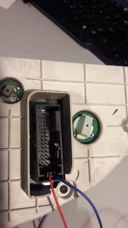
    At the moment, as you can see in the picture, I have determined the location of the 4 pins.

    The bottom two are + 12V, GND
    The top two are CAN.

    My guess is that for people familiar with the subject, these are trivial questions, but when searching the internet resources I did not find an answer about the pin markings of the meter plug, so I do not even know which pin number 2 is :) Statistically, it's 2-4 possibilities.

    Rather, I try not to give voltage to the system without PCB analysis, so as not to damage it.
    In addition, even if I had to give something to pin 2, I do not know what value of this voltage should be?
    12V or 5V?

    If possible, please ask for a "question to a friend" :) and more information.

    Added after 15 [minutes]:

    Samuraj wrote:
    When it comes to the counter for 508 and 3008, the matter is completely different here. The appropriate data frame activates the counter. Without this frame, which is fed in periodically, the counters go to sleep.


    I already thought that I would not pull on this topic. I have too little input.
    While I can handle communication via CAN, unfortunately I have no idea where to get information about the structure of frames and data contained in them. I could scan all possible combinations, but it's probably not the best idea.

    Probably one salvation for me will be finding a working car - donor connection of a simple CAN logger on the MCP2515 / ESP32 and the use of mathematical statistics as in the case of the BIONX engine :)

    First engine start after CAN
    www.mmp24.pl/bldc/bionx_pierwsze_udane_uruchomienie_silnika.m4v

    But where can I find such a car and who will let me in ...?
    If I were a beautiful blonde it might be easier ... but luckily I'm not :)
  • ADVERTISEMENT
  • Helpful post
    #6 17031670
    ste
    Level 28  
    Mondeo MK3 odometer:
    Pin 17 - ground
    Pin 1 - 12V fixed (terminal 30)
    Pin 2 - 12V "after ignition" (terminal 15)

    This along with what you have already determined should be enough for you to turn on the counter.
  • #7 17032275
    kordian2
    Level 10  
    ste wrote:
    Mondeo MK3 odometer:
    Pin 17 - ground
    Pin 1 - 12V fixed (terminal 30)
    Pin 2 - 12V "after ignition" (terminal 15)

    This along with what you have already determined should be enough for you to turn on the counter.


    Such an effect!
    Step forward :)

    Ford / Mondeo / MK3 Speedometer - CAN - I need data about the meter pinout


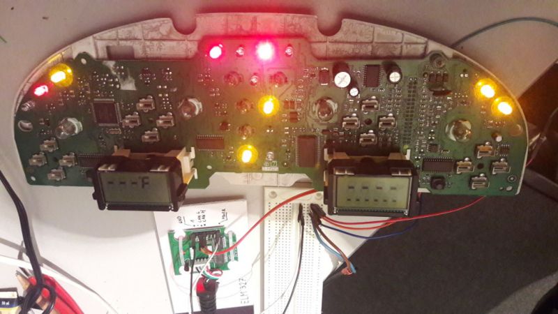
    After connecting pin 2 to 12V, the LEDs light up immediately.
    At the moment of supplying power, the displays do not show anything, only after several seconds they wake up and you can see what is in the picture.
    In addition, the left switch changes the temperature unit from F to C, so it concludes that the microcontroller is working.

    Now I will see if there are any frames on the CAN bus because maybe the meter sends its status from time to time.
  • ADVERTISEMENT
  • #8 17032297
    szymitsu21
    VIP Meritorious for electroda.pl
    What is your action aimed at?

    When it comes to frames, the easiest and fastest way to get them is from a roadworthy car.
  • #9 17032530
    kordian2
    Level 10  
    Education is my main goal.
    This thread is a side topic and when I manage to achieve satisfactory results and set the counter, it will serve as a demonstration of the CAN bus for my main thread, i.e. engine control in the BIONX system.
    In my opinion, there is no cheaper (from PLN 10) and more effective CAN terminal than a car meter.

    Further analysis:
    After connecting the oscilloscope, the transmission is visible, hence the conclusion that, as I assumed, the meter is already sending something to the CAN bus.
    After connecting the MCP2515, I got one type of eight byte dataframe with ID = 0x430
    Code: C / C++
    Log in, to see the code

    The above frame is repeated approximately 10 times per second.
    Maybe now for the test I will send some data to the above address and see if the meter responds.

    Added after 1 [hours] 22 [minutes]:

    There is a first breakthrough!
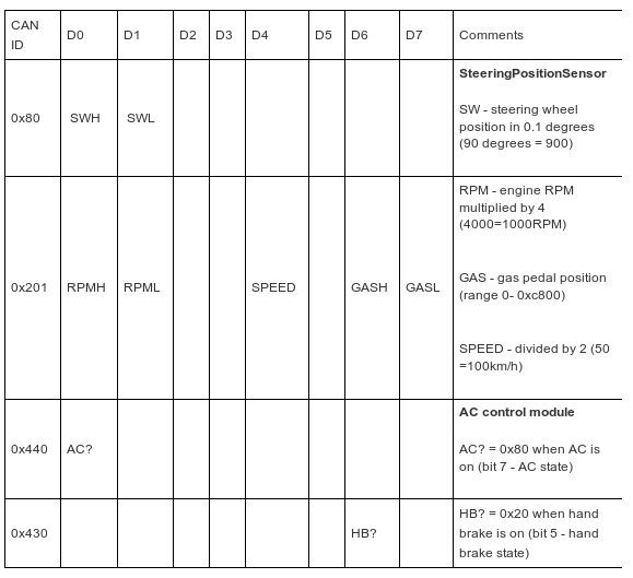
    I manage to steer the RPM pointer :)
    The site helped me
    www.electronicsworkshop.eu/FordMondeoCANhacking
    Ford / Mondeo / MK3 Speedometer - CAN - I need data about the meter pinout
  • #10 17033417
    szymitsu21
    VIP Meritorious for electroda.pl
    connect any tester and do a selective test of elements.

    You'll see everything you can :)
  • ADVERTISEMENT
  • #11 17033442
    abart64
    Level 33  
    There is a test option in this counter. You have to turn on the ignition while holding the right button until the word "test" appears on the right LCD. By pressing the button the various functions appear one after the other. The first is the meter test, i.e. all the tips and controls.
  • #12 17033993
    kordian2
    Level 10  
    szymitsu21 wrote:
    connect any tester and do a selective test of elements.

    You'll see everything you can :)


    It was in this configuration, ie "scanner mode", that I was physically working yesterday :)
    Using a simple program, I performed a scan in the ID range and incremented each of the eight bytes by sending five the same frames to be sure.

    Due to the fact that I always wonder how to make my work easier / more difficult, I thought (idea not yet implemented) that I would connect the IP camera and record changes on the meter display and when there is a change in the image, it will save the current values of ID, DATA from CAN.
    There is probably not much of it, but yesterday I could not determine which register is responsible for controlling the fuel level indicator and engine temperature.

    At the moment, I am able to activate the counters speed and rpm . engine and battery indicator lights and turn on the so-called "odometer", i.e. the two lower displays, the left one shows the temperature of -40oC and the right one the meter reading / Km and TRIP, i.e. the trip sub-meter.

    My guess is that the meter status (kilometers traveled) will not be controlled by CAN because it is closely related to some EEPROM register of the microcontroller and to reset this value you would have to plug into the MC programming pins.

    Ford / Mondeo / MK3 Speedometer - CAN - I need data about the meter pinout

    When I was looking for information about the counter, I found a photo and a video of such "hooking"


    The car has something like 90,000 on the meter so it looks interesting and I don't need to "twist" :)

    summarizing .
    The counter is functional and I managed to wake it up by supplying 12V to pin 2.
    After waking up, the frame ID 0x430 (content in the news above) appears on the CAN bus.
    I can control RPM and SPEED hints via ID 0x201
    The two lower displays were activated, but without activation and the 2 indicators (battery, engine fault).

    I cannot control the fuel gauge and engine temperature.

    Added after 2 [minutes]:

    abart64 wrote:
    There is a test option in this counter. You have to turn on the ignition while holding the right button until the word "test" appears on the right LCD. By pressing the button the various functions appear one after the other. The first is the meter test, i.e. all the tips and controls.


    Thanks for the information.
    A very interesting test option.
    Maybe at the same time it sends CAN frames responsible for changes on the meter?
    I'll check today.
  • #13 17034119
    ste
    Level 28  
    Quote:
    I cannot control the fuel gauge and engine temperature.


    I think that you will not control the fuel gauge via CAN, because it is controlled directly from the level sensor in the tank (information about the amount of fuel is not sent to the meter via CAN). That is, the fuel level sensor is connected directly to the meter (pins 24 and 25). Try to connect some resistors or a potentiometer to these pins and the indicator should rise.

    The temperature is sent via CAN from the engine control unit to the meter.

    Other:
    Closed hand brake indicator light - pin 12 (ground control).
    Oil pressure sensor - pin 8 (ground control)

    Counter backlight - pin 4 (12V)
  • #14 17124746
    tomsoniasty
    Level 8  
    Good day.
    How do I control the turn signals on this counter?
    Ground, 12V or another signal?
    From what I found out, the pins from the turn signals are 18 and 19.
  • #15 18390863
    ASA22
    Level 11  
    [Quote = "ste"]
    Quote:
    I cannot control the fuel gauge and engine temperature.


    Hello
    You put on a great topic. I have a focus counter on the table and I tried to get at it too. I also have the entire installation from this model because the Focusik mk1 will soon be delivered to the steelworks. I will remove the computer and the rest of it for educational purposes.
  • #16 20078032
    dyerseve
    Level 8  
    The waveform is recorded in a separate eeprom or in a microcontroller? I have no way to correct the mileage in the new meter and I thought that I would solder the eeprom itself, as long as it is in a separate bone.
  • #17 21145747
    piotrszapanski123
    Level 2  
    >>17031670 And for CAN what pins?

Topic summary

The discussion revolves around the pinout and functionality of the speedometer for the Ford Mondeo MK3 and Hyundai Coupe, specifically regarding the CAN bus system. The user initially faced challenges in powering the speedometer, which required a secondary "after ignition" power source (terminal 15) in addition to the primary 12V supply. After identifying the pinout, the user successfully powered the speedometer and observed its operation on the CAN bus, including the transmission of data frames. Further insights were shared about controlling various indicators and the limitations of the fuel gauge, which operates independently of the CAN system. The conversation also touched on testing methods and the potential for educational applications using the speedometer as a CAN terminal.
Summary generated by the language model.
ADVERTISEMENT