FAQ
TL;DR: 4.18 V on TL_INVT_PWM with panel unplugged; "After supplying voltage on TL_INVT_PWM, the backlight appears." That points to a control-path fault around UT2/R441/LVDS on Lenovo G510 LA‑9641P. [Elektroda, nuda, post #17022006]
Why it matters: It helps techs and G510 owners fix no‑backlight issues faster by checking the right signal path.
Quick Facts
- TL_INVT_PWM is on LVDS pin 8; ~4.18 V unplugged, ~1 V spike then 0 V when the panel connects. [Elektroda, nuda, post #17022006]
- KBC EC_INVT_PWM (pin 25) shows about 3.3 V, indicating the EC is driving the control signal. [Elektroda, nuda, post #17022059]
- R441 sits near the LVDS connector; use photos or boardview to locate and probe it. [Elektroda, Stani12, post #17024663]
- Some boards lack PR441, yet the TL_INVT_PWM path remains connected across the pads. [Elektroda, nuda, post #17033459]
- When traces run in inner layers, trace with a multimeter in diode mode from LVDS to KBC/UT2. [Elektroda, sylweksylwina, post #17024320]
What is TL_INVT_PWM on the LA-9641P and what does it control?
It is the backlight control/PWM line to the panel inverter circuitry. When you manually drive TL_INVT_PWM high, the backlight turns on. If connecting the panel pulls it low, the control path is collapsing under load. That points to cabling, connector, or the signal conditioning stage. "After supplying voltage on TL_INVT_PWM, the backlight appears." [Elektroda, nuda, post #17022006]
Which LVDS pin carries TL_INVT_PWM on the Lenovo G510?
Pin 8 of the LVDS connector carries TL_INVT_PWM. Users measured a brief ~1 V pulse at pin 8 when the panel connects, followed by a drop to 0 V. With the panel disconnected, they saw a steady high level at that pin. [Elektroda, nuda, post #17022006]
Where is resistor R441 on the LA-9641P board?
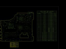
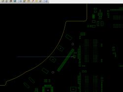
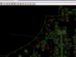
R441 is located near the LVDS connector area. Use a high‑resolution board photo or a boardview to identify it, then probe both sides for voltage and continuity. A shared screenshot marks R441’s position with an arrow for guidance. [Elektroda, Stani12, post #17024663]
My PR441 footprint is empty. Is that normal, and does the path still connect?
Yes. Some LA‑9641P boards ship with PR441 unpopulated. Technicians confirmed the TL_INVT_PWM path remains connected across the pads despite the missing part. Verify continuity across the footprint to be sure on your revision. [Elektroda, nuda, post #17033459]
How can I trace TL_INVT_PWM from KBC to LVDS without a boardview?
Use the diode‑test mode on a multimeter to follow the net across nearby resistors. An expert tip: "Search between UT2 and LVDS." Tracks can run on inner layers, so probe from the LVDS pin to surrounding passives, then toward KBC and UT2. [Elektroda, sylweksylwina, post #17024320]
What should I see on KBC pin 25 (EC_INVT_PWM)?
Expect about 3.3 V at KBC pin 25 if the EC is asserting the backlight control. If that node is healthy while TL_INVT_PWM collapses at the LVDS, the fault lies between EC/KBC output and the LVDS pin. [Elektroda, nuda, post #17022059]
Why does TL_INVT_PWM read high unplugged but drop when the panel connects?
Unplugged, the line sits high because no load pulls it down. When the panel connects, the path likely sinks the line, disabling backlight. Users observed a brief ~1 V pulse then a drop to 0 V on connect. [Elektroda, nuda, post #17022006]
How do I check the LVDS ribbon for a TL_INVT_PWM short or load?
Measure resistance from TL_INVT_PWM to ground with and without the ribbon connected. Reported readings of roughly 124–128 kΩ indicate no hard short. A much lower value suggests a loading fault in the cable or panel circuitry. [Elektroda, nuda, post #17031702]
Will reflashing BIOS or EC/KBC fix the no‑backlight condition?
A BIOS reflash did not restore TL_INVT_PWM in this case. Before reflashing the EC/KBC, confirm EC_INVT_PWM is present and trace continuity toward the LVDS. Firmware changes rarely fix a pulled‑low PWM line. [Elektroda, nuda, post #17022006]
Should I replace UT2 to restore the PWM signal?
Treat UT2 replacement as a last resort. One technician replaced UT2 twice and the PWM dropout persisted, forcing a board replacement. "UT2 replacement (two times) did not work." Validate the path and cable first. [Elektroda, nuda, post #17050744]
How do I open an LA-9641P .brd boardview file?
A user opened the .brd boardview using an Allegro program and shared screenshots. Install Cadence Allegro Free Viewer or a compatible viewer to inspect nets like TL_INVT_PWM and locate R441 quickly. [Elektroda, Stani12, post #17024515]
Could the LVDS cable or the panel be causing the PWM to collapse?
Yes. Measure the ribbon for shorts and open lines before swapping boards. If measurements are inconclusive, try a known‑good cable or panel to isolate the load that pulls TL_INVT_PWM low. Provide the panel model when seeking help. [Elektroda, Stani12, post #17033864]
Is forcing TL_INVT_PWM high a valid test?
Yes, as a quick diagnostic. Manually driving TL_INVT_PWM high made the backlight appear, proving the backlight power chain worked. Do not leave it forced; fix the control path instead. [Elektroda, nuda, post #17022006]
I cannot find R431/PR401 on my board. Is that expected?
It can be. Some resistors are unmarked or unpopulated on certain LA‑9641P revisions. One user noted PR401 was not populated, and TL_INVT_PWM routing differed from the schematic expectation. [Elektroda, nuda, post #17024974]
What’s a concise workflow to diagnose TL_INVT_PWM loss on G510?
- Check EC_INVT_PWM at KBC pin 25 for ~3.3 V.
- Trace TL_INVT_PWM from LVDS pin 8 through R441/PR441 using diode‑test.
- Measure TL_INVT_PWM‑to‑GND resistance; swap cable or panel if it loads the line. [Elektroda, sylweksylwina, post #17024320]


