logo elektroda
logo elektroda
X
logo elektroda

How to eliminate transient state of I/O pins during ESP8266 module boot?

Maryush 2742 24
ADVERTISEMENT
Treść została przetłumaczona polish » english Zobacz oryginalną wersję tematu
  • #1 17096737
    Maryush
    Level 22  
    Welcome,

    I am designing a controller for a WiFi controlled AC motor based on an ESP8266 12E module. The motor has left/right rotation. The actuators are relays. When the controller is connected to the power supply, both relays switch on for a moment, which causes the motor to want to run in both directions simultaneously and for that moment it heats up considerably. How do I eliminate this problem? The result is supposed to be that the ESP pins controlling the relays when the controller is activated are supposed to be in a low state all the time, and not change state to high, then back to low again.
  • ADVERTISEMENT
  • #2 17096773
    Brivido

    Level 34  
    Show an executive diagram? What kind of motor is it, etc. For induction motors and contactors, they should have a mechanical interlock.
  • #3 17096805
    Maryush
    Level 22  
    This is a motor for a roller shutter. Standard relay control, with a BC848 transistor from the I/O port of the ESP module.
  • #4 17097074
    AIIoT
    Level 11  
    Maryush I read about this problem once, but I didn't think it posed any real problem, maybe you should try treating the microcontroller as a regular button and use so-called hardware debounce'ing (to eliminate contact vibration) before the base of the transistor.

    using a program I wrote to test hardware emulation of contact vibration available at:
    http://aiiot.c0.pl/web/2018/02/01/program-do-testowania-sprzetowej-eliminacji-drgania-stykow/ .

    How to eliminate transient state of I/O pins during ESP8266 module boot? .
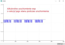
    I have noticed that this transient does indeed occur, and it is possible to get rid of it with the MAX6818 circuit, but whether this option is viable for this purpose is another question, maybe it is enough to analyze the operation of this circuit and reproduce it only to the extent where the oscillation will not occur (just adding a capacitor and resistor will not help)
    How to eliminate transient state of I/O pins during ESP8266 module boot?
  • ADVERTISEMENT
  • #5 17097155
    mpier
    Level 29  
    Maryush wrote:
    This is a motor for a roller shutter. Standard relay control, with a BC848 transistor from the I/O port of the ESP module.
    .
    With "standard relay control" the motor will not behave as you wrote, if the relays are working. Show the schematic. Have you tried on other pins?
  • #6 17097198
    Maryush
    Level 22  
    The transient problem when the ESP is powered applies to all I/O pins, just as colleague AIIoT has shown in the oscilloscope diagram. I don't know if applying left and right turns to the motor at the same time can hurt it, if not then it won't be a problem in my case, but if it is, then the problem is already there. The specification for this drive does not give details as to what the protections are.
  • #7 17097293
    mpier
    Level 29  
    Are you sure? If so, the relays are broken ;-) .
  • #8 17097374
    Maryush
    Level 22  
    Why would the relays be broken? The relay coils are switched, exactly as the diagram shows.
  • ADVERTISEMENT
  • #9 17097440
    Loker
    Level 39  
    I see several possibilities:
    1. Hardware elemination of transients on I/O pins - e.g. some RC filters - it would be useful to know the frequency and duration of these transients; besides, this type of filter will introduce a delay during normal operation.
    2. some logic to prevent the relays from switching on simultaneously - this will not change the fact that during transients the relays will switch on for a while (not simultaneously) - this will cause the motor to "jerk", which is not desirable.
    3. delayed activation of the relay power supply - the ESP power supply is applied first, the relay coils power supply with some (e.g. 1s) delay.
  • #10 17097477
    Maryush
    Level 22  
    Colleague Loker has analysed and worked out the subject very nicely.
    The best solution would be option 3, i.e. first the ESP will turn on and then the power supply will be applied to the relay coils. It has to be some small IC/circuit because I have practically no space on the board at the moment. Maybe something on an NE555?
  • ADVERTISEMENT
  • #11 17097708
    krzysiek_krm
    Level 40  
    Hello,
    Maryush wrote:
    that is, first the ESP will turn on and then the power plus is applied to the relay coils
    .
    maybe a typical "reset" circuit - small, cheap, etc.

    Regards
  • #13 17097731
    mpier
    Level 29  
    Maryush wrote:
    Why would the relays be broken? The relay coils are switched, exactly as the diagram shows.
    .
    If you have wired everything up correctly, and they are triggering both directions at the same time, then they may be faulty. This is independent of the ESP8266.

    Are these transients for real? On every pin? Even if you were controlling a low state on the output?

    Without a schematic, it's difficult to give you sensible advice.
  • #14 17097750
    Maryush
    Level 22  
    They are not faulty because I have a diode on one of the outputs and it too lights up momentarily when the ESP is switched on, this module has that. I will be testing a solution with a transistor controlled by an RC circuit.
  • #15 17097755
    krzysiek_krm
    Level 40  
    mpier wrote:
    Maryush wrote:
    Why would the relays be broken? The relay coils are switched, exactly as the diagram shows.
    .
    If you have wired everything up correctly, and they are triggering both directions at the same time, then they may be faulty. This is independent of the ESP8266.

    On a slightly different note - the author probably made a minor conceptual error: he used one relay left and another right . Should have used one relay left - right and another start - stop . Which doesn't change the fact that transients will cause uncontrolled switching of these relays during the CPU ramp up.
  • #16 17097851
    mpier
    Level 29  
    This is hardly possible. After all, the author wrote that he "connected in a standard way". That is, as you wrote, either the NO contacts of the second in series with the NC of the first, or yet another way. Which pins does the author use for control?
  • #17 17097853
    Maryush
    Level 22  
    If I had known there were transients, I would have given one relay to change the direction of rotation and another to turn on/off. Then the drive would only spin clockwise or counterclockwise when the ESP is activated.
    Control on pins 14 and 16.
  • #18 17098094
    AIIoT
    Level 11  
    Maryush At the very beginning I would suggest you try to change the control method, during start-up the ESP has mainly a high state.
  • #19 17098433
    Slawek K.
    Level 35  
    And what is your colleague writing the program in ? in arduino ? do the pins have states (LOW or HIGH - depending on the logic of the circuit controlling the relays) set at the start of the programme ? for this, appropriate pulldown or pullup resistors and there should be no problems.
    Pin 13 is the RX pin of uart1, so maybe this is the problem.

    https://i.pinimg.com/originals/0c/8c/e8/0c8ce8bc22ee6ba0e2ed830bcbb28454.png


    Greetings
  • #20 17098442
    krzbor
    Level 27  
    See the topic I am promoting (in the footer). This solution certainly works.
  • #21 17098643
    Maryush
    Level 22  
    krzbor wrote:
    See the topic I am promoting (in the footer). This solution definitely works.
    .
    Very well described, if there is a clear on any of the ESP8266 12E pins at startup, this control can be done. I'll also try with adding pull-up resistors to zero, but I don't think that will do anything.
  • #22 17098745
    krzbor
    Level 27  
    I have given the waveforms - you can see that there is a stable signal on Rx (GPIO3). At my place this circuit controls the garage door and the entrance gate. It has never opened by accident yet.
  • #23 17101031
    Maryush
    Level 22  
    The resistors were of no use. I will do the control indirectly through an optocoupler and it should be fine. Does the ESP8266 12E have a second UART? I would like to use the first one for communication with the Atmega and the second one for debugging. I am writing the programs in arduino.
  • #24 17101479
    krzbor
    Level 27  
    Regarding the second UART you didn't quite read my promoted topic :) Someone asked this question there too. I don't understand why you didn't use the way you did with the Rx line - when connected via the 3k3 resistor to ground, was there any signal on that output during startup?
  • #25 17101651
    mpier
    Level 29  
    Maryush wrote:
    Resistors were of no use.
    The first resistor from the left you have connected in reverse. The second is too large or the internal pull-up is too powerful. Count for yourself what came out at the base of the transistor. If pin 16 is in the high state (google it) you will sooner burn it out than pull it down to ground. You probably don't want to do that very much.

Topic summary

The discussion addresses the issue of transient high states on ESP8266 12E module I/O pins during boot, which cause both relays controlling a bidirectional AC motor to activate momentarily, risking motor damage. The motor is controlled via standard relay circuits driven by BC848 transistors from ESP pins 14 and 16. Transients occur on all I/O pins at startup, causing unintended relay activation. Proposed solutions include hardware debouncing with RC filters, implementing logic to prevent simultaneous relay activation, and delaying relay coil power supply after ESP boot using small ICs such as NE555 timers or reset circuits. Pull-up or pull-down resistors were tested but found ineffective. An optocoupler-based indirect control is considered to isolate and prevent transient effects. The ESP8266 12E’s UART pins and their startup states were discussed, with suggestions to avoid using pins with default high states or UART functions for relay control. The possibility of using one relay for direction and another for start/stop to avoid simultaneous activation was also mentioned. Overall, the consensus favors delaying relay power or isolating relay control to eliminate harmful transient states during ESP8266 boot.
Summary generated by the language model.
ADVERTISEMENT