Elektroda.com
Elektroda.com
X

HP 15 - AC134NW - Does not charge, does not start, nothing lights up

damian13m 4926 17
This content has been translated flag-pl » flag-en View the original version here.
  • #1
    damian13m
    Level 6  
    Hello,
    Laptop: HP Pavilion 15 - AC134NW
    Motherboard Markings AHL50 / ABL52 LA-C701p Rev: 1.0
    The hob does not turn on, neither on the battery nor the power supply, and no LEDs are on.
    I noticed that the chip with the signature PU2 is heating up on the board and I cannot identify it, its designation is BA 2F 520 (it is marked in the photo) HP 15 - AC134NW - Does not charge, does not start, nothing lights up .
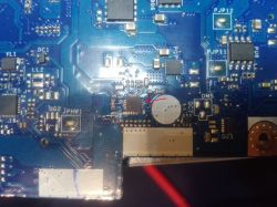
    Could someone help me find the problem, or if someone had a diagram or some voltages what should be on this system, then he could give me a measurement?
    Best regards and thank you in advance for your help :D
  • #2
    JayRo
    Level 35  
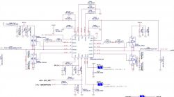
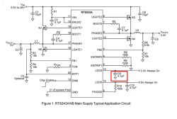
    PU2 is a 3.3V / 5V Richtek RT8243AZQW converter, a fragment of the diagram can be found e.g. in the diagram from LA-A998P under PU301.
  • #3
    boro1234567
    IT specialist
    damian13m wrote:

    I noticed that the chip with the PU2 signature is heating up on the disc and I cannot identify it with its marking BA 2F 520 (marked in the photo)

    PU2 is RT8243AZQW inverter driver, code 8A .
    It is possibly heating up due to LDO overload.
    damian13m wrote:
    Could someone help me find the problem, or if someone had a diagram or some voltages what should be on this system, then he could give me a measurement?

    In the attachment you have a pdf of the layout.
    Measure, publish the results.
  • #4
    lisek
    Service technician RTV
    There is no MS or boardview.
    After HP solutions, others are based on the same systems.
    Read e.g. Link

    Broadwell series cpu, e.g. i3-5010U (SR23Z)
    KB9022Q x, where x: revision
    SPI Bios 25L6473EM
    charger PU201 (bq 735 / 725A)
    RT9711BGJ5 (BA) switch USB
    PU2 to RT8243A (8A)
    PU4 G5719C, 1.05V
    US1 SY6288D20AAC

    It fits e.g. Compal LA-C501P / LA-B181P (there are modifications to the KBC system) / LA-A998P / ...

    You have the PU2 work system, i.e. "what heats up" 8A = RT8243AZQW, signal:
    - EC_ON goes to KBC pin 112
    - MAINPWON goes to KBC pin 104.
    HP 15 - AC134NW - Does not charge, does not start, nothing lights up
  • #5
    damian13m
    Level 6  
    Hello,
    Thank you all for guiding me to what system it is (I'm a beginner in motherboard diagnostics).
    I measured the voltage on the system and it looks like this:
    from 1 to 6 pin has nothing;
    on 7pin - 4.75;
    from 8 to 10 there is nothing;
    on 11pin - 19.7;
    on 12pin - 4.5;
    at 13 nothing;
    on 14pin - 4.9;
    on 15pin - 0.7;
    from 16 to 18 nothing;
    on 19pin - 4.7;
    at 20 nothing.

    lisek wrote:
    You have the PU2 work system, i.e. "what heats up" 8A = RT8243AZQW, signal:
    - EC_ON goes to KBC pin 112
    - MAINPWON goes to KBC pin 104.

    There is nothing on pin 13, i.e. this system does not start KBC?
  • #6
    boro1234567
    IT specialist
    damian13m wrote:

    on 15pin - 0.7;

    You have the wrong voltage here, it should be 3.3V.
    It probably includes the NCB.
    A short-circuit test will explain everything.
  • #7
    damian13m
    Level 6  
    boro1234567 wrote:
    A short-circuit test will explain everything.

    And how to make such an attempt?
  • #8
    boro1234567
    IT specialist
    damian13m wrote:

    And how to make such an attempt?

    Do you have a power supply with current and voltage regulation?
  • #9
    damian13m
    Level 6  
    boro1234567 wrote:
    Do you have a power supply with current and voltage regulation?

    I only have voltage regulation but no current regulation.
  • #10
    boro1234567
    IT specialist
    damian13m wrote:

    I only have voltage regulation but no current regulation.

    Unsuitable.
  • #11
    damian13m
    Level 6  
    boro1234567 wrote:
    Unsuitable.

    And if I had such a power supply, how should I do this test?

    Added after 15 [minutes]:

    I think I found the culprit, it is the capacitor marked in the picture
    HP 15 - AC134NW - Does not charge, does not start, nothing lights up
    Both sides have continuity with ground
  • #12
    boro1234567
    IT specialist
    damian13m wrote:
    Both sides have continuity with ground

    Desolder it and check it.
    I bet it's not him.
  • Helpful post
    #13
    lisek
    Service technician RTV
    You have (90%) a kbc
  • #14
    damian13m
    Level 6  
    Hello,
    Recently I bought a laboratory power supply and it turned out that there is a short circuit on the kbc system, I desoldered the system and ordered a new one. And from what I read, this kbc needs to be programmed to work. Can I do it with a CH341A programmer (because I have the same one so far).
  • #15
    boro1234567
    IT specialist
    damian13m wrote:
    Can I do it with a CH341A programmer (because I have the same one so far).

    You don't need a dedicated programmer for the KBC.
  • Helpful post
    #16
    lisek
    Service technician RTV
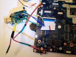
    He's on the net Link description how to program KB9012 (9010 and 9016 have the same pin "y) using CH341.
    The website of the manufacturer CH341 (http://wch.cn)

    Quote:
    KB9010, KB9012, KB9016 - pins for programming identical
    42 - KSO3, 59 - KSI4, 60 - KSI5, 61 - KSI6 and 62 - KSI7

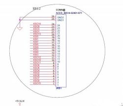
    Having a schematic of the platform (board) can either be done through the programmer or keyboard connector
    * as long as the pins 59,60,61,62 and 42 kbc KB901x are led out to the connector.
    :idea: :!:
    Connect the programmer and board weights to each other!
    Apply 3.3V from the programmer to the pin. kbc power supply / or use external. power supply
    _________________________
    e.g. for LA-8224p
    * for ease of work (no soldering to the board) you can use org. ribbons for the keyboard badge
    Spoiler:
    HP 15 - AC134NW - Does not charge, does not start, nothing lights up

    Spoiler:
    HP 15 - AC134NW - Does not charge, does not start, nothing lights up

    that is on the keyboard
    KSO3 - 22 pin, KSI4 - 15 pin, KSI5 - 19 pin, KSI6 - 16 pin and KSI7 - 17 pin

    Interesting about CH341 Link
  • #17
    damian13m
    Level 6  
    Only I need to program KB9022QD. And this is the instruction for kbc901x
  • Helpful post
    #18
    lisek
    Service technician RTV
    Watch out for this forum Link
    :!: especially the answer # 19 15 Nov 2018 09:44 (lower part of answer ..)