logo elektroda
logo elektroda
X
logo elektroda

[Solved] ESP01 - LEDs do not light up when connected according to the diagram

wiesslaw 1677 6
ADVERTISEMENT
Treść została przetłumaczona polish » english Zobacz oryginalną wersję tematu
  • #1 17163018
    wiesslaw
    Level 7  
    Hello.
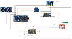
    In the project as in the diagram:ESP01 - LEDs do not light up when connected according to the diagram after connecting everything as I have drawn, the diodes on esp01 do not light up at all.
    Is this a normal condition ? It is necessary to run the module programmatically first ?

    When connecting the module via usb converter to the computer, the red diode is constantly on, and at the beginning the blue diode lights up and flashes for a while. Then the communication with the module via the serial port monitor and AT commands works.

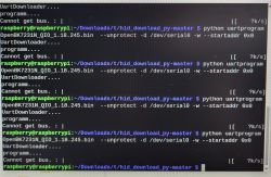
    And here is the kind of error I get when I try to upload some esp related code to the arduino nano.
    ESP01 - LEDs do not light up when connected according to the diagram .
    Do you have a problem with Arduino? Ask question. Visit our forum Arduino.
  • ADVERTISEMENT
  • #2 17163152
    BlueDraco
    MCUs specialist
    Powered devices work better.
  • ADVERTISEMENT
  • #3 17163165
    wiesslaw
    Level 7  
    And what is wrongly connected that you write that there is no power?
  • ADVERTISEMENT
  • Helpful post
    #4 17163172
    pawel1148
    Level 24  
    I have some doubts about this diagram. The module does not light up because it probably does not get power. In the schematic someone has incorrectly connected the power supply to the ESP module via a 10Kohm resistor(VCC pin).
    Connect the VCC pin from ESP01 directly to 3.3V from the inverter, CH_PD can remain connected via this resistor.
  • #5 17163188
    wiesslaw
    Level 7  
    Well on the schematic it was not someone who marked it but me, it is my schematic 😁 and in fact I can already see that I pasted in the wrong place both on the schematic and soldered in the circuit a resistor. It was supposed to be behind the 3.3V cable splitter. Thanks !

    Added after 12 [hours] 47 [minutes]: .

    pawel1148 wrote:
    .
    Connect the VCC PIN from ESP01 directly to 3.3V from the inverter, CH_PD can remain connected via this resistor.

    But do this already with two separate wires or branch one but before the resistor ?
  • ADVERTISEMENT
  • Helpful post
    #6 17167790
    krzbor
    Level 27  
    Connect the power supply to VCC, and from it via a resistor to CH_PD. Be careful with the SIM800L - it's all about the antenna. There is really high power there, enough to interfere with the other processors. Keep the antenna away from the ESP for a start. ESP12s are better - there's an extra protective housing there. Don't assume that if you put it in a small enclosure everything will work too.
  • #7 17934662
    wiesslaw
    Level 7  
    Quote:
    PIN VCC from ESP01 directly to 3.3V from inverter
    solving the problem :) .

Topic summary

The ESP01 module's LEDs do not light up when connected according to the provided schematic because the module likely does not receive proper power. The schematic incorrectly places a 10KΩ resistor in series with the VCC pin, which should instead be connected directly to a stable 3.3V supply. The CH_PD pin can be connected via a resistor to VCC. Correcting the wiring by removing the resistor from the VCC line and ensuring direct 3.3V power resolves the issue. Additionally, when using modules like SIM800L alongside ESP01, antenna placement is critical to avoid interference due to high power emissions. ESP12 modules offer better protection with their housing. The problem with uploading code to an Arduino Nano related to ESP communication was also noted but not detailed. The solution involved correcting the power supply wiring to the ESP01 module.
Summary generated by the language model.
ADVERTISEMENT