logo elektroda
logo elektroda
X
logo elektroda

ESP-07 does not respond to flashing - what could be the reasons?

mmaker 1065 8
ADVERTISEMENT
Treść została przetłumaczona polish » english Zobacz oryginalną wersję tematu
  • #1 18085279
    mmaker
    Level 19  
    Hello, I have a problem with my ESP. About a year ago I bought 2 pieces for testing purposes, I made a simple UART TTL adapter for them with a voltage converter to 3.3V (BSS138) because I needed to test the UART - WIFI bridge. Everything worked until the last time I used them (about a year ago) and now I can't upload any sketch with the Arduino IDE. I downloaded the previous sketch with the arduino IDE from: https://circuits4you.com/2018/01/01/esp-to-esp-communication/

    I tried to upload the factory soft from the manufacturer with the ESP8266Flasher program and of course it doesn't go. I changed different baudrates which didn't help either. When trying to upload the firmware I give GPIO15, GPIO0 pins to ground and GPIO2 to 3.3V via a 10K resistor. Both LEDs on the module light up and when I open the COM port on the putty I have the same bushes being sent from the ESP. It is not possible to either upload another firmware or erase the memory. I also omitted the adapter I made and spliced everything together on a spider, powering the module from a lab power supply. Still the same symptom. Have I managed to whip up the ESP?

    I would also add that every time I boot from the flash memory the ESP from the sketch I uploaded a year ago is called back....
    Do you have a problem with Arduino? Ask question. Visit our forum Arduino.
  • ADVERTISEMENT
  • #2 18085316
    khoam
    Level 42  
    mmaker wrote:
    When trying to upload firmware I give GPIO15, GPIO0 pins to ground and GPIO2 to 3.3V via a 10K resistor.
    .
    Do you have the REST and EN (CH_PD) pins connected via a resistor to 3V3?

    Added after 1 [minute]:

    mmaker wrote:
    I'll also add that every time I boot from flash memory, the ESP from the sketch I uploaded a year ago is called back...
    .
    It's not likely to have whisked away, quite so ;) .

    Added after 8 [minutes]:

    mmaker wrote:
    When trying to upload firmware to ground I give GPIO15, GPIO0 pins
    .
    GPIO15 should be connected to ground all the time through a 10k resistor, not just during firmware upload. GPIO0 should be shorted to ground during upload.
  • ADVERTISEMENT
  • #3 18085501
    mmaker
    Level 19  
    khoam wrote:
    Do you have the REST and EN (CH_PD) pins connected via a resistor to 3V3?
    Yes I have these pins connected via 10K resistors to 3.3V.

    mmaker wrote:
    GPIO15 should be connected to ground all the time through a 10k resistor, not just during firmware upload. GPIO0 should be shorted to GND during upload.
    GPIO15 I have connected to GND permanently but without resistor. GPIO0 I have via a 10K resistor to 3.3V and directly from GPIO I have a small switch connected to GND

    I enter UART programming mode by short-circuiting GPIO 0 to GND and applying power to the ESP, both LEDs light up then and something tells me the blue one should be flashing....
  • #4 18085532
    khoam
    Level 42  
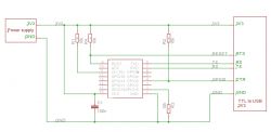
    If the circuit you're programming in looks like the diagram below and you haven't confused RX with TX, it's somewhat likely that you have a messed up RX pin in the ESP. Have you ever applied a signal to the RX pin in 5V logic?

    ESP-07 does not respond to flashing - what could be the reasons? .

    Added after 4 [minutes]: .

    mmaker wrote:
    Into UART programming mode I enter by shorting GPIO 0 to GND and applying power to the ESP,
    .
    The power can be on all the time, and even should be. Only GPIO0 is shorted to GND for programming time.
  • ADVERTISEMENT
  • #5 18085559
    mmaker
    Level 19  
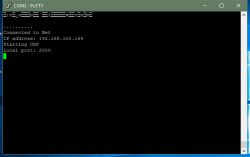
    Hmm actually I can't remember if I managed to apply 5V to any of the pins because the board only has the pins needed for UART transmission and programming connected, the rest is not connected and as far as I can remember everything worked as expected until the very end. I have TX and RX connected OK because when starting the previous skit with ESP on Putty I have:
    ESP-07 does not respond to flashing - what could be the reasons? .

    Connecting the second module I have UART -> WIFI -> UART communication between them.

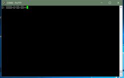
    If I short-circuit the GPIO0 pin to GND and apply power to the module then I receive bushes sent by the module continuously - Putty at 115200 baud
    ESP-07 does not respond to flashing - what could be the reasons? .

    any other setting of other BAUD gives the same results and this on both modules :) I don't know what else I could be doing wrong
  • ADVERTISEMENT
  • #6 18086320
    khoam
    Level 42  
    mmaker wrote:
    If I short-circuit the GPIO0 pin to GND and apply power to the module, I receive screams sent by the module continuously - Putty at 115200 baud
    .
    Set putty to 74880. feed power to ESP, do not short circuit GPIO0 to ground. Are you then receiving meaningful information?
  • #7 18086370
    kaczakat
    Level 34  
    Of the many ESP8266 ac I have found the ESP-07 to be dead, you may have just experienced this. It stopped programming a year ago, but there are messages to let you know, and it's not like nothing is happening. It uploads, it uploads, then the errors and error message fly (Arduino + core 2.5 + full messages enabled while compiling and uploading). I tried again last week and ONCE managed to upload the blink at 9600 speed, but the rest are failures.
    Buy yourself a board for 2£ for the ESP8266, or make some connections yourself 15 through a 10k resistor to GND, 0 10K to VCC, CH_PD 10k to VCC, RST 10k to VCC, you can apply voltage by holding the button and shorting 0 to GND or having the chip already powered up you do RST while holding GPIO0 shorted to GND. Enable full messaging when uploading and retype the text the Arduino throws out.
    Helpful post? Buy me a coffee.
  • #8 18086777
    mmaker
    Level 19  
    Hello Gentlemen, a foolish man was born and I think a foolish man will remain. I apologise in advance for the confusion and admit my mistake. I swore that everything was ok in the connections but it wasn't! I looked at the PCB adapter pattern on the computer 5 or 6 times, I even checked the connections to see if everything was ok and it turned out that it wasn't ok and that was from the beginning.... And today freshly I look at the PDF, cycle and there it is, everything works. The cause was shorting to GND the wrong GPIO to ground. Forgive me the error :cry: .
  • #9 18087027
    kaczakat
    Level 34  
    It very often helps to disassemble everything into a box, forget about it for a few days and plug everything back in, without repeating previous mistakes. The important thing is that it works.
    Helpful post? Buy me a coffee.

Topic summary

The discussion revolves around troubleshooting issues with the ESP-07 module, which is not responding to firmware flashing via the Arduino IDE. The user initially connected the necessary pins for programming but faced difficulties in uploading sketches. Responses highlighted the importance of proper connections, specifically ensuring GPIO0 is grounded during upload and GPIO15 is connected to ground permanently. Suggestions included checking for potential damage to the RX pin, ensuring correct baud rates, and verifying connections against the schematic. Ultimately, the user discovered a wiring error, which resolved the issue, emphasizing the need for careful inspection of connections.
Summary generated by the language model.
ADVERTISEMENT