 .
.
We have practically always used a simple USB to UART converter based on the popular CH340 chip to program IoT devices. Recently, however, I realised that you could just as well program wirelessly using a second Wi-Fi module and a UartTCP driver with an additional script that either resets the module or sets the boot state, depending on the platform. This is a potentially attractive and simple solution, as it does not require implementing the programmer from scratch, simply redirecting the UART traffic. Here I will present the first version of this mechanism.
The old programming method .
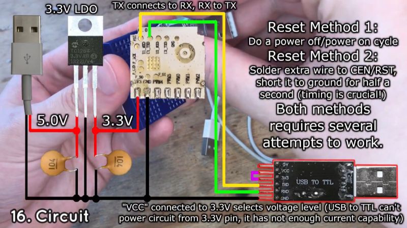
Up to now, we have connected the chip to be programmed to the computer via the USB port on the UART, and then our flasher communicates with it via this port. Depending on the type of MCU being programmed, we also had to short-circuit the boot pin to ground or power, for example, or reset the chip. It looked more or less like this:
 .
.
(although this 5 V could be taken from the 5 V pin from the USB to TTL converter).
New programming method .
The new idea is to replace the USB to UART converter with a second Wi-Fi module with already pre-loaded our firmware , compiled with the UART driver enabled on TCP. It should be noted here that this method requires soldering wires to the device to be programmed anyway. It does, however, have other advantages:
- you do not need a USB to UART converter
- you can program the hardware without connecting it to a PC/laptop, so there is no risk of short-circuiting - you can power the programmed hardware from the mains
- potentially boot mode control and resetting are easier - not every USB to UART converter has extra RTS/DTR lines, and the Wi-Fi module has many IOs we can use
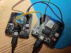
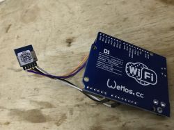
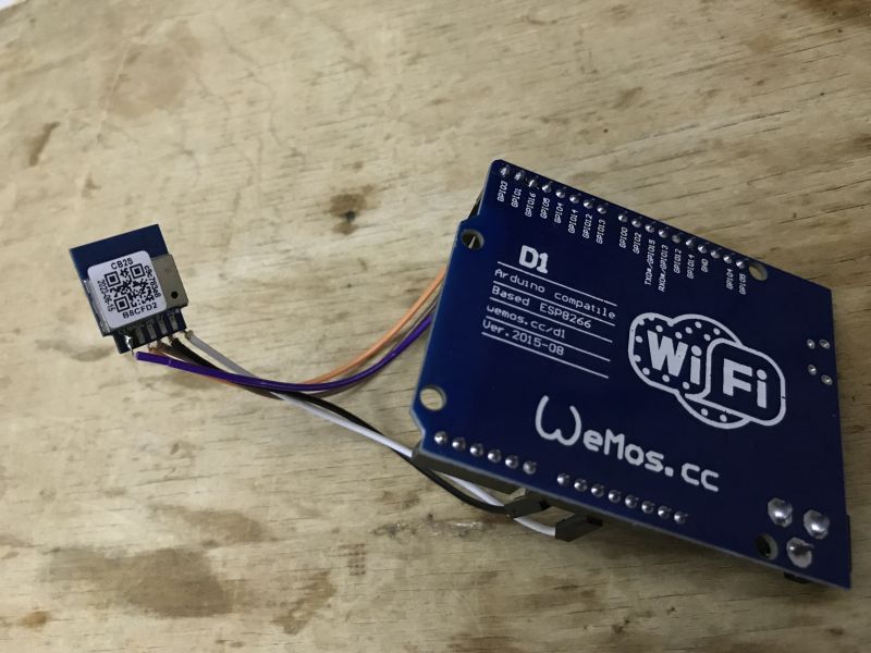
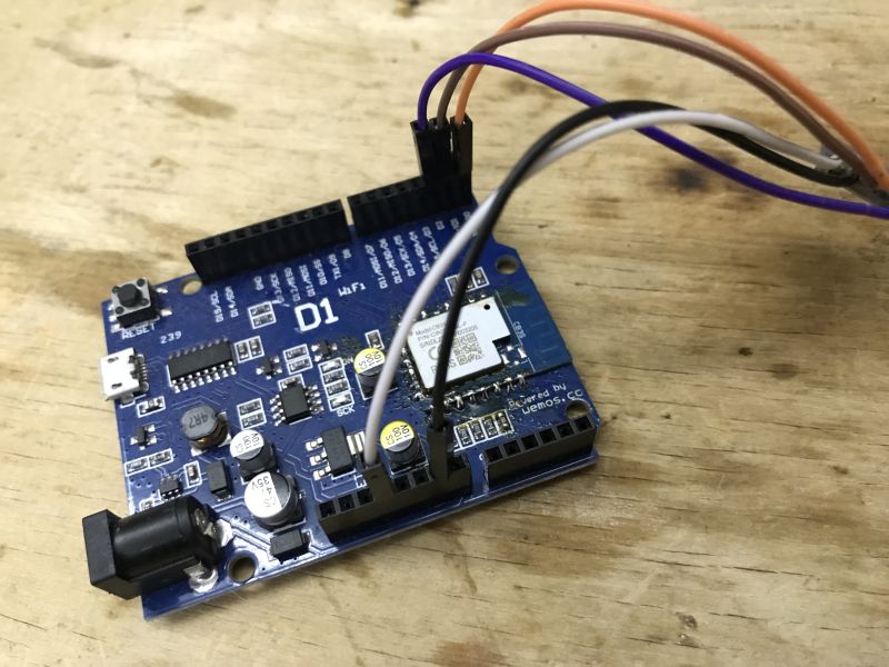
This is what an example connection looks like - the CB3S on the board from the Arduino Wemos is the programmer, and the CB2S hanging on the wires is the chip being programmed. Of course, you can do it the other way round - use an additional small CB2S soldered to the device to program it with. You just need to connect properly:
- RX to TX (usually RX1, TX1)
- TX to RX (usually RX1, TX1)
- common ground
- common supply 3.3 V
- any GPIO configured as "Relay" in OBK from programmer to CEN pin of the chip being programmed (to reset)
 .
.
 .
.
Implementation details .
Pass this paragraph if you are only interested in results!
We already have in OpenBeken the TCP to UART bridge driver - when started, it opens a port on TCP port 8888, and everything that goes into that port is passed to UART port 1 of the Wi-Fi module. The same works in the other direction too. This was already used in our redesign of the Zigbee gateway .. This could potentially carry the programmer's data over the network.
The OBK also, of course, has programmable GPIO operations, so we can have control over resetting and CEN of the chip.
The only thing left is to plug in the flasher, the source code can be found here:
https://github.com/openshwprojects/BK7231GUIFlashTool
First of all, the flasher must take the IP address and port of the device-programmer instead of the COM port. This is not a problem, however, you need to somehow run the controller on this programmer. The Tasmota command interface will be used for this. An example command is sent as a GET request like this:
http://192.168.0.212/cm?cmnd=add_dimmer%20-10
In a similar way, a command can be sent that starts the TCP driver on the UART and sets the baud. In my C# it looks like this:
Code: C#
The driver is stopped and restarted, this is so that the baud can be changed. 8192 is the buffer size.
The second problem is the CEN operation - resetting the BK7231, because you can only start programming the BK7231 right after the reset. The window of opportunity is very short.
I also perform this by command:
    void toggleCEN()
    {
        SendCommand(TARGET_IP, "setChannel 0 0");
        SendCommand(TARGET_IP, "setChannel 0 1");
    }
This assumes that there is a pin on channel 0 in OBK with the Relay role, and this pin is connected to the CEN of the device being programmed.
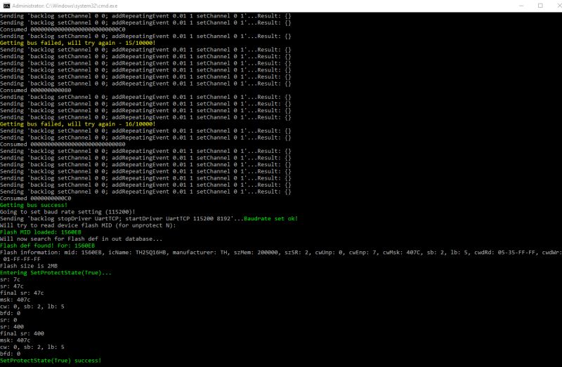
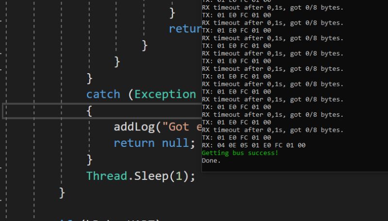
Catching the flashing mode (aka "getting bus") takes a bit then anyway, so I may have to improve this mechanism, but at least it works.
 .
.
The rest of the changes are down to swapping the serial port for a TCP socket.
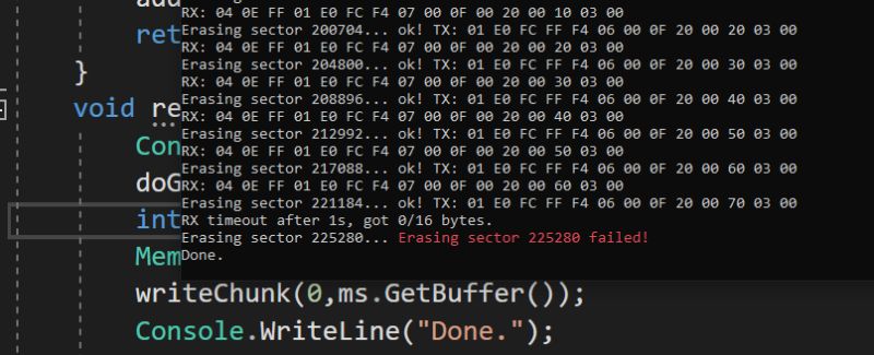
The stability issue remains - the Wi-Fi isn't as reliable as the cable though, and I've seen that sometimes one of the flash commands doesn't execute correctly - I've added a retry transmission mechanism for this reason.
 .
.
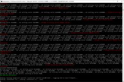
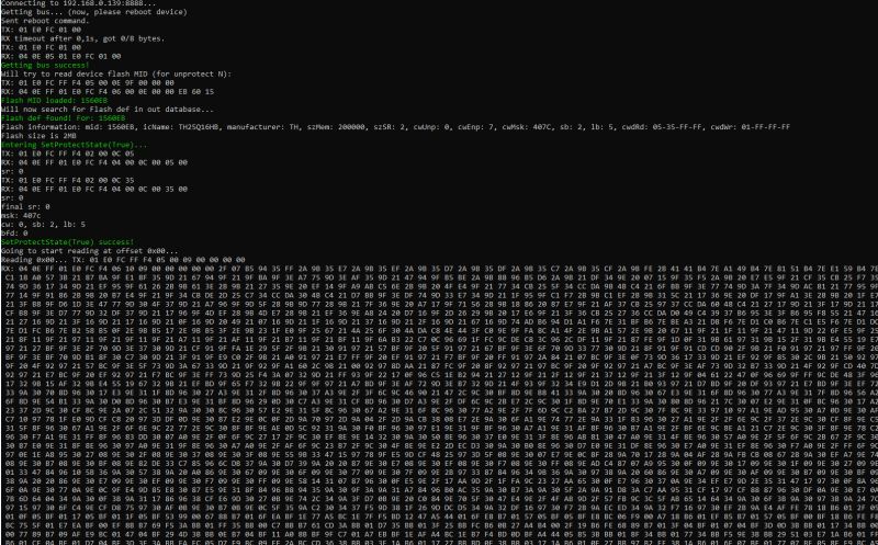
This is what the whole process looks like for flash operations, here reading:
 .
.
ADVERTISEMENT
Verify operation .
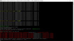
Smallest test command - draws the data, writes it to the target, then reads it and compares it to the one at the beginning:
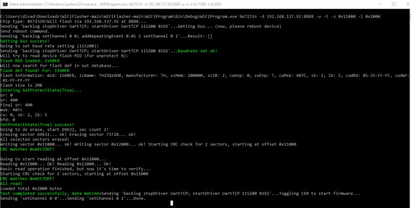
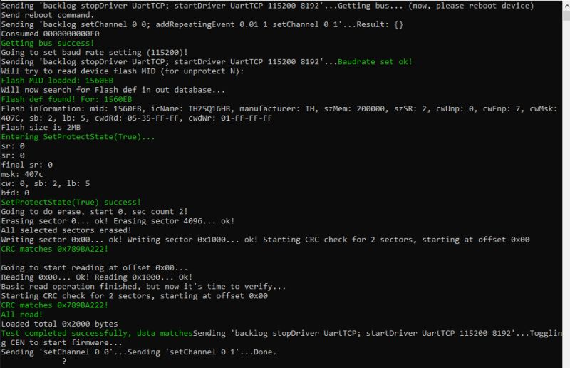
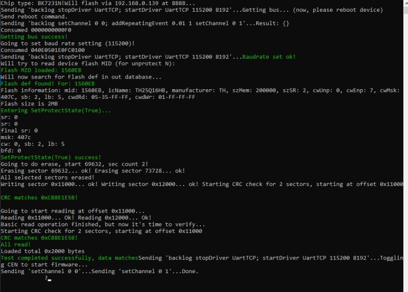
WiFiProgram.exe bk7231n -d 192.168.0.139:8888 -u -t -s 0x11000 -l 0x2000
In the screenshot is the result from the same but with offset 0, i.e. bootloader editing on BK7231N. This is not possible on the BK7231T - this will lose the ability to program via the UART and SPI will have to be used.
 .
.
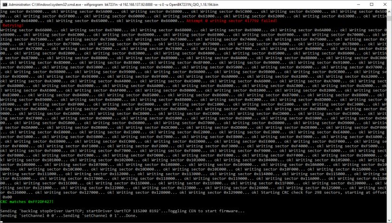
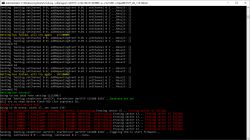
Same test for offset 0x11000 (application start):
 .
.
Supported commands .
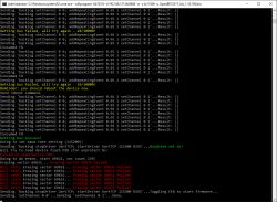
The new flasher has basic commands to operate on the flash. These include reading memory, writing, verification (comparison with a given file) and a memory test based on writing and reading a random sequence of bytes. A short readme follows:
usage: wifiprogram bk7231n [-h] [-d DEVICE] [-s STARTADDR] [-l LENGTH] [-b BAUDRATE]
                   [-u] [-r] [-w] [-p]
                   filename

OBK WiFi Downloader.

positional arguments:
  filename              specify file_crc.bin

optional arguments:
  -h, --help            show this help message and exit
  -d DEVICE, --device DEVICE
                        Target device, default 192.168.0.1:8888
  -s STARTADDR, --startaddr STARTADDR
                        burn flash address, defaults to 0x11000
  -l LENGTH, --length LENGTH
                        length to read, defaults to 0x1000
  -b BAUDRATE, --baudrate BAUDRATE
                        burn uart baudrate, defaults to 921600
  -u, --unprotect       unprotect flash first, used by BK7231N
  -r, --read            read flash
  -w, --write           write flash
  -t, --test            test flash (generate pattern, write, read, verify)
  -v, --verify           verify flash


        Flash BK7123N (-w, --write, start address 0x0)
        wifiprogram bk7231n -d 192.168.0.139:8888 -w -s 0 -u OpenBK7231N_QIO_1.18.193.bin
        Read BK7231N (-r, read):
        wifiprogram bk7231n -d 192.168.0.139:8888 -r -s 0 -l 0x200000 firmwarebackup.bin
        Short test (-t, --test, start address 0x0, len 0x2000):
        wifiprogram bk7231n -d 192.168.0.139:8888 -u -t -s 0 -l 0x2000
        Long test (1MB random data):
        wifiprogram bk7231n -d 192.168.0.139:8888 -u -t -s 0 -l 0x100000
Repository:
https://github.com/openshwprojects/WiFiFlasher
The "getting bus" operation takes quite a long time, I don't know how to get the timings correct. The flasher on the UART has no such problem with this. This is an issue to be solved.
Further plans .
This option will be integrated into the main flasher:
https://github.com/openshwprojects/BK7231GUIFlashTool
Ultimately, I will test this with plaforms other than BK7231.
Summary .
Being able to use a second Wi-Fi module as a programmer has its pros and cons. The pros include better automation of the process (not every USB to UART converter has extra lines to control possible RESET/CEN/BOOT pins), flashing a device connected to the network (many IoT devices have non-isolated converters, so you can't just program them with the main power connected) and convenience (no need to pull a USB cable). Of the downsides at the moment, I can see a potential problem with the get bus operation, but this only applies to Beken, and trouble with less precise timing in general - this is to be determined.
It's worth bearing in mind that the whole thing could be greatly improved by implementing the flasher on the target Wi-Fi chip, as at the moment it's simply in the role of TCP bridge to UART, but that may be some day.
@divadiow @insmod let us know if it works for you.
PS: Newer versions may be available here: https://github.com/openshwprojects/WiFiFlasher
Cool? Ranking DIY Helpful post? Buy me a coffee.


