logo elektroda
logo elektroda
X
logo elektroda

[Solved] JBL Flip 3 - Won't turn on or charge, no response please help.

kacperos9371 37344 44
ADVERTISEMENT
Treść została przetłumaczona polish » english Zobacz oryginalną wersję tematu
  • #1 17217610
    kacperos9371
    Level 14  
    Hello.
    I bought a jbl flip 3 speaker that would not turn on.
    Initially, I thought that the problem was with the battery or the micro usb socket, but both of these parts turned out to be working.
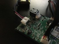
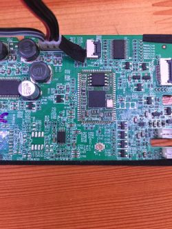
    In the loudspeaker you can see that someone has been transferring the battery connector.
    Holding the power switch for 30 seconds does not give anything, nor does connecting the charger.
    When you click the power button, the lights around it will only flash and that's it.
    Below are the voltage measurements.
    On the power switch before switching on 4.05 v, after pressing 0 v.
    The battery is 4.17v - regardless of the button combination, the voltage does not drop.
    Tensions on the board:
    vcc to gnd 3.283 v
    csb to gnd 3.278 v
    miso, clk, mos 0v
    vcc for mos, clk, miso 3.118 v
    All these voltages are available after pressing the power button, without pressing the voltages.

    I am asking for help in finding the fault and where to look for it, best regards.
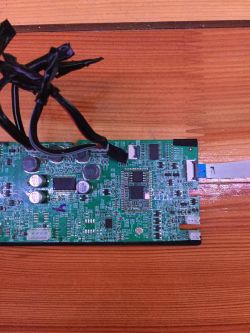
    Photos in the attachment because normally would not stick.
    https://filmy.elektroda.pl/83_1526068234.mp4
  • ADVERTISEMENT
  • #2 17218262
    mariuszw19640717
    Level 35  
    kacperos9371 wrote:
    I am asking for help in finding the fault and where to look for it, best regards.

    Check if the 10V converter is functional, if there is no this voltage, the terminal may be damaged and it causes the converter not to start, or the converter itself is damaged.
    This device is so complicated that the possibilities and reasons for its inoperability are "thumping", and the measurements and SM should make it easier to find the damage.
  • ADVERTISEMENT
  • #3 17222193
    kacperos9371
    Level 14  
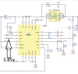
    On the U7 MP9428 chip, pin 3 is 3.85 V.
    On the Q1 MTB04N03 chip, pins 5, 6, 7, 8 are 3.78 V, pins 1, 2, 3 are 4.18 V, and pin 4 is 4.07 V.


    JBL Flip 3 - Won't turn on or charge, no response please help.
  • #4 17222590
    mariuszw19640717
    Level 35  
    kacperos9371 wrote:
    On the Q1 MTB04N03 chip, pins 5, 6, 7, 8 are 3.78 V, pins 1, 2, 3 are 4.18 V, and pin 4 is 4.07 V.

    And for pin 1,2 Q2?
  • #5 17222667
    kacperos9371
    Level 14  
    Q2 on pins 1 and 2 no voltage.
    In addition, I found one, probably a capacitor, missing on the U1 board. It may be preventing you from turning on.
    JBL Flip 3 - Won't turn on or charge, no response please help.
  • #6 17223089
    mariuszw19640717
    Level 35  
    kacperos9371 wrote:
    Q2 on pins 1 and 2 no voltage.

    Did you measure to weight?
    Measure on the basis of Q3.
    What is R 505 combined with?
    kacperos9371 wrote:
    In addition, I found one, probably a capacitor, missing on the U1 board.

    Give its designation from the diagram, because from this photo it is impossible to determine which capacitor it is.
  • #7 17223947
    kacperos9371
    Level 14  
    This is how I measured pin 1, 2 to ground and it was about 8 mV on pin 3 3.7 V
    Today I measured pin 1, 2 a second time and, surprisingly, it is 423 mV on pin 3, then 3.7 V. Earlier I measured it well so I do not know where this voltage is suddenly. Pin 1, 2 of Q2 to Q3 3.3V base.
    R 505 connects to pin 27 (Deep_Sleep) on the U1 chip.
    Unfortunately, as for the capacitor on the board, there are no markings in the diagram, only the entire U1 circuit is marked
  • #8 17224052
    mariuszw19640717
    Level 35  
    kacperos9371 wrote:
    Unfortunately, as for the capacitor on the board, there are no markings in the diagram, only the entire U1 circuit is marked

    Which pin U1 is this capacitor connected to?
    Check if there is anything sticking to the ground on the 10V line.
    In the "diode" range of the meter, measure, the red probe to pin 1 or 2 of Q2, and the black probe to ground, just disconnect the power supply before measuring.
  • ADVERTISEMENT
  • #9 17224782
    kacperos9371
    Level 14  
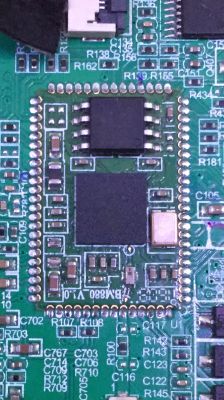
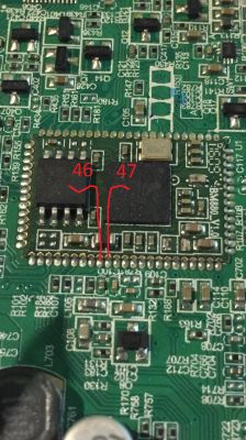
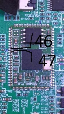
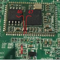
    The broken capacitor on U1 is connected with one pad to pin 46 and 47 and the other goes to the bga circuit.
    I do not see short circuits on the 10 V line.
    Black ground / red pin 1 value increases to 3 volts then the meter displays .OL
    The red ground / black pin 1 is 0.5 V. All tests without batteries.
    Q2 pin 1 to plus bat 4.3v
    Q2 pin 1 to whip ground from 8-500 mV.
  • #10 17225065
    mariuszw19640717
    Level 35  
    kacperos9371 wrote:
    The broken capacitor on U1 is connected with one pad to pin 46 and 47 and the other goes to the bga circuit.

    According to the diagram, it does not connect to pin 46, but to pin 47 C107 100nF.
    It looks like something with the U1 is wrong, damaged, or there is no power.
  • #11 17225833
    kacperos9371
    Level 14  
    After applying the meter to the capacitor pad, it squeaks at pins 46 and 47 U1
  • #12 17225918
    mariuszw19640717
    Level 35  
    kacperos9371 wrote:
    After applying the meter to the capacitor pad, it squeaks at pins 46 and 47 U1

    I don't know if it should be connected or not, no board drawing, give me a picture.
  • #14 17226294
    mariuszw19640717
    Level 35  
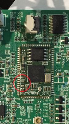
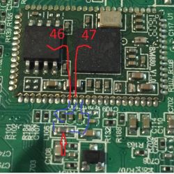
    Maybe mark these points.
  • #15 17226307
    kacperos9371
    Level 14  
    JBL Flip 3 - Won't turn on or charge, no response please help. [img-0]JBL Flip 3 - Won't turn on or charge, no response please help.
  • #16 17226993
    mariuszw19640717
    Level 35  
    This capacitor on pin 46 is not to be and is not there, and it is on pin 47, which is good.
    kacperos9371 wrote:
    After applying the meter to the capacitor pad, it squeaks at pins 46 and 47 U1

    I don't know how you measured it, but if there is a short circuit between pin 46 and 47, the system is damaged.
  • #17 17227476
    kacperos9371
    Level 14  
    Now what can you do if it is damaged?
  • #18 17227895
    mariuszw19640717
    Level 35  
    kacperos9371 wrote:
    Now what can you do if it is damaged?

    I do not know.
    I see such a system for the first time, both in the diagram and in the photo, I was looking for some information about it, but I didn't find anything, maybe I'm looking for it wrong.
    Ask in the services, maybe they will fix it.
  • Helpful post
    #19 17227926
    Qudlatyy
    Level 17  
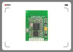
    https://pl.aliexpress.com/item/BTA-RX-SPDIF-C...eceive-module-module-aptx-ll/32817066513.html

    this broken "capacitor" is actually a coil on the power line of the CSR8670 chip

    If there is no short to ground on both pads of this coil, it is enough to make a jumper in this place If there is a short circuit on one of these pads, the module should be replaced


    edit

    pins 46 and 47 are connected to each other via r185 having a value of 0 ohms

    there should be 1.8V to ground
  • #20 17228173
    kacperos9371
    Level 14  
    Thank you very much to Mr. Qudlatyy for your help.
    After making the bridge, the loudspeaker turns on at this point! :D
    There is only one little problem. The loudspeaker only works when I hold power, it turns off immediately after releasing it.

    Edit: The problem with switching off, however, may be related to a bad contact in the place of the bridge.
    What coil should be soldered there? About what parameters?

    Added after 46 [minutes]:

    And one more question, solder it with a station or a hotair?
  • #21 17228712
    mariuszw19640717
    Level 35  
    kacperos9371 wrote:
    After making the bridge, the loudspeaker turns on at this point!

    So the diagram has nothing to do with what is on the board.
    L105 is the black element that connects to the jumper you soldered and there was probably a jumper (zero resistance) there, which is the power circuit.
    What is the voltage on this armature?
    kacperos9371 wrote:
    The loudspeaker only works when I hold power, it turns off immediately after releasing it.

    Because there is probably another damage and the protection turns off the device so that there is no more damage and that is why the jumper has been removed by someone.
  • #22 17230090
    Qudlatyy
    Level 17  
    3.3V power flows through the L105 to pin 45 and 48. On pin 47 there is 1.8V coming from the U1 chip, which through the R185 resistor goes to the leg 46 It is used to power the memory MX25U3235

    JBL Flip 3 - Won't turn on or charge, no response please help.


    kacperos9371 wrote:
    And one more question, solder it with a station or hotair?


    make a jumper in the place of the missing element, there can be a wire, solder the station with a thin tip

    What is the voltage on pin 5 of the U5 chip with the power button pressed and the power button released?
  • #23 17230126
    kacperos9371
    Level 14  
    With the power button released, the voltage is 0 V.
    While pressed 3.3V.
  • #24 17230220
    Qudlatyy
    Level 17  
    If I understand correctly it should be like this:
    With the button pressed, VCC_switch_3V3 appears and the system starts
    at this point, R434 should show a high state, i.e. I assume 3.3V which causes Q7 conduction and thus maintains a low state (zero V) on pin 1 of Q5
    Zero V on pin 1 of Q5 keeps it conductive and everything works

    Please check the voltage on the R434 when you turn on the power button
  • ADVERTISEMENT
  • #25 17230321
    mariuszw19640717
    Level 35  
    Qudlatyy wrote:
    3.3V power supply for pins 45 and 48 flows through the L105.

    Yes, in the diagram, and on the board, which pins are they?
  • #26 17230500
    Qudlatyy
    Level 17  
    JBL Flip 3 - Won't turn on or charge, no response please help.

    On the board as in the diagram
  • #27 17230739
    kacperos9371
    Level 14  
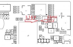
    Please check the voltage on the R434 when you turn on the power [/ quote] button

    3.14 V on the left and 13 mV on the right.
    JBL Flip 3 - Won't turn on or charge, no response please help.
  • #28 17230975
    Qudlatyy
    Level 17  
    Check the R434 value should be around 47kOhm, you can measure without desoldering
    If ok then measure the voltage on R438, R439, R440.
  • #29 17231062
    kacperos9371
    Level 14  
    The R 434 has 46.89 KOhm OR OK.
    R 439 bottom 3.2 V, top 0.7 V, R 438 bottom 0.6 V, top 0.5 V, R 440 bottom and top 0.7 V.
  • #30 17231137
    Qudlatyy
    Level 17  
    Do you have a PCB connected with the vol + and vol- keys?

Topic summary

The discussion revolves around a JBL Flip 3 speaker that fails to turn on or charge. The user initially suspected issues with the battery or micro USB socket, but both were confirmed functional. Voltage measurements indicated potential problems with the internal circuitry, particularly around the U1 chip and associated components. Various users provided troubleshooting steps, including checking the 10V converter, measuring voltages at specific pins, and identifying a missing capacitor. A critical breakthrough occurred when a jumper was made to replace a broken component, allowing the speaker to power on, although it required holding the power button. Further issues with Bluetooth connectivity were resolved by correctly identifying button functions. Ultimately, the speaker was successfully repaired, although some users reported ongoing issues with different units.
Summary generated by the language model.
ADVERTISEMENT