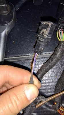
Hi
I installed a manual pull-out hook (line). I recently bought a used Westfalia 1K0 907 383 towbar module.
I have a bundle (supposedly the original one removed from such a car), instructions found on the Internet and dozens of "read" topics on forums. The problem is, I can't get to the end of the wiring harness.
My beam looks like this:
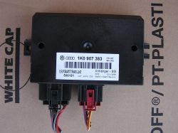
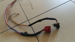
The wiring harness from the fuse box side is as follows:
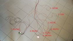
As for the scheme, I am trying to adapt:
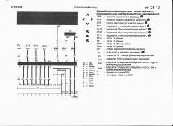
And almost all the wires are there, except for the 4, 5, and 6 in the photo. But it is black and green in the diagram and it is not in the bundle.
Could I please help me identify and connect these wires?
-------------------------------------
Update:
I found a description like this:
B bundle, i.e. the one connected to the car (red 12-pin plug):
Pin 2 - blue and black 0.5 (cable color and thickness) - fuse box C (the one in the car on the driver's side) place 4, i.e. 12 V after ignition (I had to solder to the wire already there)
Pin 3 - black and red - 0.5 - BCM J519 plug C (beige, first on the right) pin 17 - stop light signal - soldered to the already existing cable
Pin 7 - orange-green 0.35 - BCM J519 plug C pin 15 - CAN - soldered to the already existing cable
Pin 8 - orange-brown 0.35 - BCM J519 plug C pin 16 - CAN - soldered to the already existing cable
Pin 9 - purple-red 2.5 - fuse box B (in the engine compartment) I, to make it easier, I connected to the free place of box C
Pin10 - brown 1.0 - ground point near the hook module mounting location
Pin11 - gray-yellow 1.5 - fuse box C position 25 - fixed 12 V
Pin12 - White / Red 1.5 - Fuse box C position 23 - fixed 12 V
https://www.vwgolfv.pl/viewtopic.php?f=53&t=3546&start=30
The other wires, connected to the little black 4-pin plug and relay, are probably lowering the hook from the button. I do not have it, so I will probably leave it unconnected.
I am not closing the topic yet, we will see how it goes tomorrow or the day after tomorrow (depending on how it will be with free time).
I installed a manual pull-out hook (line). I recently bought a used Westfalia 1K0 907 383 towbar module.
I have a bundle (supposedly the original one removed from such a car), instructions found on the Internet and dozens of "read" topics on forums. The problem is, I can't get to the end of the wiring harness.
My beam looks like this:


The wiring harness from the fuse box side is as follows:

As for the scheme, I am trying to adapt:

And almost all the wires are there, except for the 4, 5, and 6 in the photo. But it is black and green in the diagram and it is not in the bundle.
Could I please help me identify and connect these wires?
-------------------------------------
Update:
I found a description like this:
B bundle, i.e. the one connected to the car (red 12-pin plug):
Pin 2 - blue and black 0.5 (cable color and thickness) - fuse box C (the one in the car on the driver's side) place 4, i.e. 12 V after ignition (I had to solder to the wire already there)
Pin 3 - black and red - 0.5 - BCM J519 plug C (beige, first on the right) pin 17 - stop light signal - soldered to the already existing cable
Pin 7 - orange-green 0.35 - BCM J519 plug C pin 15 - CAN - soldered to the already existing cable
Pin 8 - orange-brown 0.35 - BCM J519 plug C pin 16 - CAN - soldered to the already existing cable
Pin 9 - purple-red 2.5 - fuse box B (in the engine compartment) I, to make it easier, I connected to the free place of box C
Pin10 - brown 1.0 - ground point near the hook module mounting location
Pin11 - gray-yellow 1.5 - fuse box C position 25 - fixed 12 V
Pin12 - White / Red 1.5 - Fuse box C position 23 - fixed 12 V
https://www.vwgolfv.pl/viewtopic.php?f=53&t=3546&start=30
The other wires, connected to the little black 4-pin plug and relay, are probably lowering the hook from the button. I do not have it, so I will probably leave it unconnected.
I am not closing the topic yet, we will see how it goes tomorrow or the day after tomorrow (depending on how it will be with free time).


