logo elektroda
logo elektroda
X
logo elektroda

DUM-E - a simple robot arm based on the Arduino Uno

thepawel1211 6207 15
ADVERTISEMENT
Treść została przetłumaczona polish » english Zobacz oryginalną wersję tematu
  • DUM-E - a simple robot arm based on the Arduino Uno

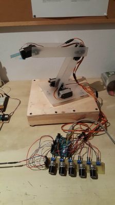
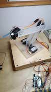
    Hello, I present to you a project that I have been working on for the last year. It is a 5-axis manipulator based on the Arduino Uno board. I started the project with the desire to develop my existing skills and learn new things about robotics.

    Mechanics

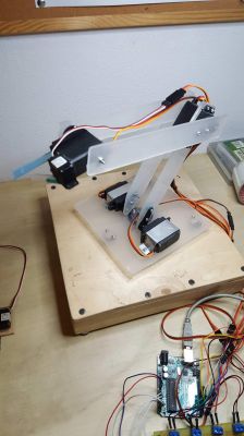
    The base is made of plywood and two boards fixed with screws. The rest of the arm is made of 3mm thick plexiglass. I also installed three small wheels for stabilization at the base. The servos I used are TowerPro MG946R and Redox S90.

    Electronics

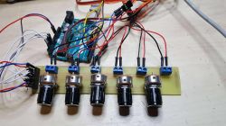
    The robot's brain is an Arduino Uno board with a program written by me. The arm is controlled by a board with 1k potentiometers, which I designed and made myself.

    In the future, I plan to improve the gripper and perhaps add another servo to make it rotate.

    Pictures:
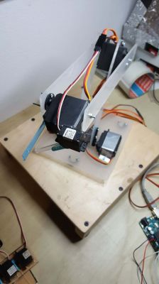
    DUM-E - a simple robot arm based on the Arduino Uno DUM-E - a simple robot arm based on the Arduino Uno DUM-E - a simple robot arm based on the Arduino Uno DUM-E - a simple robot arm based on the Arduino Uno

    Movie:

    [movie: 8f813b3e5c] https://filmy.elektroda.pl/55_1549409807.mp4 [/ movie: 8f813b3e5c]

    Code:

    Code: C / C++
    Log in, to see the code

    Cool? Ranking DIY
    Do you have a problem with Arduino? Ask question. Visit our forum Arduino.
    About Author
    thepawel1211
    Level 9  
    Offline 
    thepawel1211 wrote 4 posts with rating 12. Been with us since 2013 year.
  • ADVERTISEMENT
  • #2 17751864
    piotrva
    VIP Meritorious for electroda.pl
    1. As you have already digested the plate, you could make connectors for servos on it and make it in the format of an Arduino overlay.
    2. The arm is part of the Arduino? I can see that he is standing next to him :D
    Moderated By _lazor_:

    Let's not be crap ...

  • ADVERTISEMENT
  • #3 17751873
    thepawel1211
    Level 9  
    1. You're right, I didn't think of it!
  • ADVERTISEMENT
  • #4 17752181
    korystor
    Level 19  
    A very nice projector is born, you can even try to control the cnc and instead of a gripper give a marker pen to draw paths or even a mini drill, etc. Plusik.
  • #5 17753024
    SylwekK
    Level 32  
    Maybe a video of the action, because I have some comments, but I would like to support them constructively ;-)
  • #6 17753304
    hawryszka
    Level 12  
    This is a poor description for a project that was carried out for a year. You could make more effort.
  • #7 17753703
    h3c4
    Level 15  
    It's good that this arm is straight because it would work so crookedly; )
  • #8 17755191
    andrzejek23
    Level 19  
    piotrva wrote:
    1. As you have already digested the plate, you could make connectors for servos on it and make it in the format of an Arduino overlay.
    2. The arm is part of the Arduino? I can see that he is standing next to him :D


    2.based on / based on

    He wrote well.
  • #9 17757553
    piotrva
    VIP Meritorious for electroda.pl
    @ andrzejek23 The point is that the arm is controlled by an Arduino - the Arduino is not an integral part of the arm. The arm is based on a structure made of plastic and plywood as well as servos.
  • #10 17757936
    thepawel1211
    Level 9  
    SylwekK wrote:
    Maybe a video of the action, because I have some comments, but I would like to support them constructively ;-)

    I have uploaded a demo video :)
  • #11 17758017
    andrzejek23
    Level 19  
    piotrva wrote:
    @ andrzejek23 The point is that the arm is controlled by an Arduino - the Arduino is not an integral part of the arm. The arm is based on a structure made of plastic and plywood as well as servos.


    You're picking on. The arm control system is an integral part of it.

    BTW:
    Based on plastic construction ...

    Moderated By _lazor_:

    Let's not be crap ...

  • ADVERTISEMENT
  • #12 17759907
    SylwekK
    Level 32  
    I like constructions where something moves and I couldn't pass by indifferently :) So you put a few words in the movie now ... From what I can see, the work of the arm is based on controlling individual channels with potentiometers. The main disadvantage is, above all, the oscillation of the structure caused by the quite rapid starting / stopping of the servo, as well as the servos themselves due to their construction and operating principle (when they have little brakes - the controller releases). If they were more powerful, the effect would not be so visible. I've been going through this a long time ago, because my first camera arm head was based on servos and I quickly changed the direction of construction.
    What can be improved? In this case, adding a ramp option should already stabilize the entire arm a bit. In the case of the current control, it is a few minutes of work and literally a few lines of code per channel more.
    As a bonus, I would expand the program with motion memory. It is also not difficult. With my first controller with joystick memory, I was also afraid of problems, and it went simpler with the first shot than it seemed :)
    Good luck!
  • #13 17759979
    thepawel1211
    Level 9  
    SylwekK wrote:
    What can be improved? In this case, adding a ramp option should already stabilize the entire arm a bit. In the case of the current control, it is a few minutes of work and literally a few lines of code per channel more.

    Could you clarify a bit what this ramp is about? :)
  • #14 17760018
    SylwekK
    Level 32  
    The ramp, i.e. here with the motors, is a smooth acceleration / braking.
  • #15 18290993
    Aimeiz
    Level 16  
    Hi.
    I can see colleagues that you are up to date with robotics.
    I passed my high school diploma in Mathematics almost half a century ago, there was not much of it in college and I lost my practice a bit.
    For someone who is up to date, the task will not be very difficult.
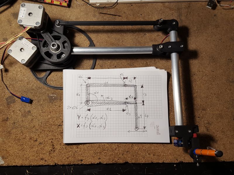
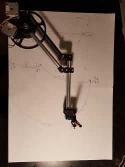
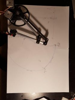
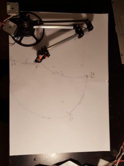
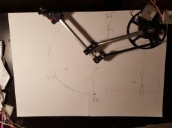
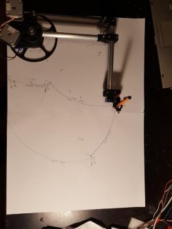
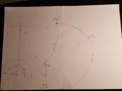
    It is about determining the functions fx and fy defining the X and Y coordinates of the end of the robot arm shown in the photo from the angles of rotation of the coaxial wheels driven by stepper motors, where the dimensions of the arm elements will be the constant coefficients.
    I need to rewrite the grbl program to control this arm.
    The dimensions are marked on the drawing. Angles between stationary elements are straight angles.


    DUM-E - a simple robot arm based on the Arduino Uno
  • #16 18291724
    Aimeiz
    Level 16  
    I will add a few more photos of how this arm works:
    DUM-E - a simple robot arm based on the Arduino Uno
    DUM-E - a simple robot arm based on the Arduino Uno
    DUM-E - a simple robot arm based on the Arduino Uno
    DUM-E - a simple robot arm based on the Arduino Uno
    DUM-E - a simple robot arm based on the Arduino Uno
    DUM-E - a simple robot arm based on the Arduino Uno


    In the last photo, the one without the device, you can see which angles I mean as arguments for the Alfa L Alfa U function. They result directly from the rotation of the stepper motors driving the arm.
    The lower gear directly drives the aluminum arm (Alfa L) and the upper gear only has a short (Alfa U) plastic arm with an axle for the plastic pusher.

    Added after 25 [minutes]:

    The problem is solvable. The Chinese made it :)
    [youtube]https://www.youtube.com/watch?v=NTBxLTUPyTU
    [/youtube]

Topic summary

The discussion revolves around a user-created 5-axis robotic arm, named DUM-E, built using an Arduino Uno board. The arm's structure is primarily made from plywood and 3mm thick plexiglass, with stabilization provided by small wheels. It utilizes TowerPro MG946R and Redox S90 servos for movement, controlled via a custom-designed board with potentiometers. Suggestions for improvement include adding a ramp function for smoother servo operation and enhancing the gripper. The user also shared a demo video of the arm in action and received feedback on the project's description and potential applications, such as CNC control or using a marker for drawing.
Summary generated by the language model.
ADVERTISEMENT