Hello my dears
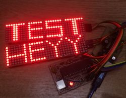
Here I will describe my experience with running an LED driver MAX7219 and a library to support it, which I developed for PIC microcontrollers. In short MAX7219 is a cube that allows you to control a very large number of LEDs using only a few microcontroller pins.
What is MAX7219?
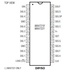
MAX7219 is a simple common cathode LED display driver capable of handling up to 64 LEDs. It is available in 24-pin DIP and SO packages. It is controlled via a 4-wire serial interface compatible with SPI. So thanks to it, we can use only a few pins of the microcontroller to control a large number of diodes. based modules MAX7219 can be connected in series with each other, while increasing the number of LEDs controlled by the same pins many times.
MAX7219 it is powered from 5V and additionally supports optional BCD coding of displayed characters. It also allows you to set the brightness of the entire segment.
The system to work does not require many external parts. The current of the displays is set with only one resistor. The specific parameters of the display, its currents and refresh rate can be read from the catalog note of the system:

What is most important to us, i.e. connecting subsequent displays on one line, so-called 'daisy chaining', looks like this:
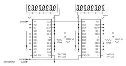
In the picture, it is worth paying attention to the combination of CLK, CS and DI/DO. The diagram also shows the connection of the remaining pins. Of course, you can also connect more than two MAX7219 chips in this way.
Purchased modules
It all started when I bought two such LED modules in a Chinese online store:
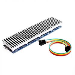
I paid PLN 14 each. The shipping was free. The package arrived quite quickly (actually two packages, because I bought each from a different seller). The displays were packed quite safely, especially for a package from China (additionally, they were in bubble wrap, you can't see it in the picture):
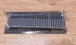
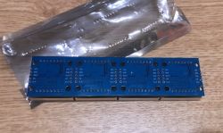
One such module consists of four separate MAX7219s and contains a total of 4 segments of 64 LEDs (256 LEDs). Still, it can be handled with only 3 microcontroller pins (CS, DATA, CLK) and two power pins. On the PCB there are pins both from the side of the connection with the MCU and from the other side where you can connect further modules:
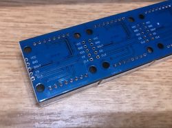
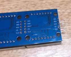
Upon closer inspection, there is a MAX7219 in an SOIC package under the LED array:
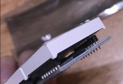
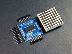
On the internet I also found a photo that shows such a module with the LED matrix removed:
Development of the library
I wrote the entire library in the MikroC PRO for PIC environment, but please don't be influenced by this - the code is quite universal and can be compiled in any C compiler. It does not use anything specific to a given environment or PIC.
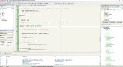
This is what it looks like when typing:
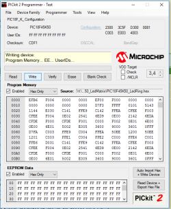
For uploading the already compiled batch to the PIC, I used the PICKIT2 software for Windows:
The hardware used looks like this:
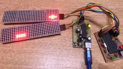
In the photo you can see my first DIY PIC programmer (PICKIT2 clone), a simple PIC18F45K50 board and two LED modules.
The PIC18F45K50 board itself has basically only the minimum needed to run this PIC, its diagram is very similar to the Pinguino 4550:
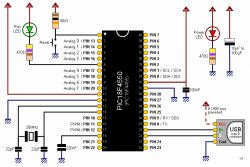
It's just that in this project I didn't use either the Pinguino environment or the hardware USB from the PIC. Well, in the diagram above there is a PIC18F4550 and not a PIC18F45K50, but they are both quite similar.
Short outline of the prepared library
Here I will present the abbreviated documentation of my library. The library is characterized by:
- support for multiple LED controllers (LED controller is presented as a structure, there are no global variables)
- the LED controller can be on any IO pins (the operation is fully programmable)
- the library does not use any functions specific to a given PIC or environment, so it should be easy to transfer to another compiler or microcontroller.
The library is made so that it allows you to connect many MAX7219 basically in three ways. They can be connected in cascade (as in the factory used module there are four connected sequentially, you can connect more), you can use the common DATA/CLK pins and only switch the selected module using CS (as the name suggests - chip select), or connect both modules quite separately, using fully separate pins. I modeled the library on similar solutions for Arduino.
The heart of the library is the structure max72XX_s which represents one LED module (i.e. several MAX7219 drivers connected together). A pointer to an object of this structure is the first argument to each of the functions described below.
The most important functions from my library are presented in the table:
| Function name | Arguments | Description |
| MAX72XX_SetupPins | led,portCS, pinCS, portCLK, pinCLK, portData, pinData | The function sets pins associated with a given LED controller. For control, 3 pins are needed - CS, CLK, Data. Each is described successively with a pointer to its port and the pin number itself |
| MAX72XX_Init | led,devices | function initializes the given LED controller. Its pins should be pre-set with MAX72XX_SetupPins. The devices parameter defines how many LED segments are connected on a given line |
| MAX72XX_setIntensity | led,address,brightness | The function sets the brightness of a given LED segment from a given controller. Brightness is expressed as a number from 0 to 16. |
| MAX72XX_shift | led, direction | The function shifts all LEDs to the right or left, i.e. allows you to perform scrolling and scrolling animations. The function correctly handles infinitely looping animations. The direction parameter can be -1 or 1. |
| MAX72XX_setLed | led,segment,column,row,status | The function sets the state of a single LED. The status can be 0 (disabled) or 1 (enabled). |
| MAX72XX_DisplayArray | led,data,size,first segment | The function allows you to display a simple graphic on given segments (8x8) LEDs. The graphics are described as a byte array - one bit corresponds to one diode. |
Specific examples of using the function are in the attachments. The above description is not intended to be 100% exhaustive, only to show what it is about.
These are not all the functions that are in the attached code, because there are also a few auxiliary functions PORT_*, which I use to handle ports, but what is described here is the most important and should be enough for most applications.
Sample code:
[syntax=c]
void main()
{
int row, col, address, i;
max72XX_t led0;
TRISA = 0; //Makes PORTB0 or RB0 Output Pin
TRISB = 0; //Makes PORTB0 or RB0 Output Pin
MAX72XX_SetupPins(&led0,&PORTA,1,&PORTA,0,&PORTA,2);
MAX72XX_Init(&led0,4);
for( row=0;row
Cool? Ranking DIY Helpful post? Buy me a coffee.


