Here you will find a practical comparison of the characteristics of online (VFI) and offline - line interactive (AVR) UPSs. Devices Micropower 1000VA and RTII 1000VA provided by the manufacturer Green Cell . We will not cover the basics of UPS here, but will focus on practical trials and experiments with this equipment. Basic information about uninterruptible power supplies can be found here: all about UPS .
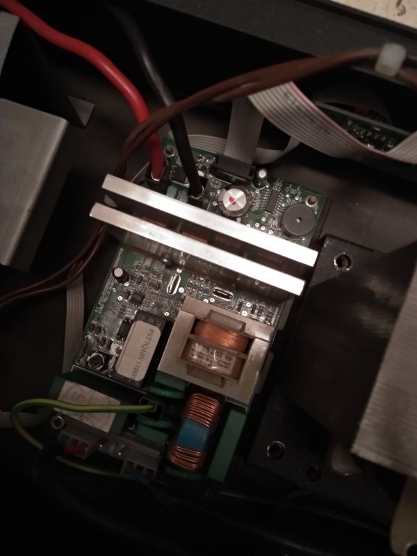
We will look inside both shared devices and compare their internal construction. In the material you will also find videos recorded during tests and after opening the housing of the devices.
Offline line-interactive UPS Green Cell Micropower 1000VA
According to the manufacturer's specification, it is a UPS with an output power of 1000VA / 600W. The energy for emergency operation is stored in two serially connected AGM 12V/7Ah batteries. In UPSs of this class, a single 12V battery is often used. The increased voltage allows you to work with less current discharging the batteries, we also get more Wh. For own needs, the emergency power supply consumes 20-50W (depending on the battery charge level). The design of the device is compact, the UPS is quiet (no forced cooling), but it is worth providing it with good ventilation to, among others extend battery life. The backlit LCD display is very readable and provides information about the operating mode, input and output voltage, battery charge level, power received from the UPS. The device has only one on/off button. Perhaps an additional UPS/battery test button would be useful?
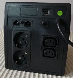
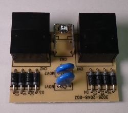
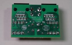
On the back of the UPS there are two types of sockets, which will be especially useful in home applications, where, apart from IEC C-13 plugs, we often meet Schuko plugs. On the rear wall there is an input circuit fuse, a USB connector for communication with the software and a surge protector with an 8P8C (RJ45) connector. In the arrester, pins 1-6 are connected, pins 4-5 are swapped. The construction is based on diodes and varistors. It can be assumed that it is a protector dedicated to FastEthernet and telecommunication devices, e.g. ADSL modems.
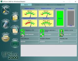
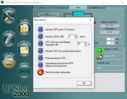
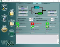
Softwareimplements the assumed functions, but in my opinion, the application interface can be slightly refreshed in the future:
Offline UPS practice tests
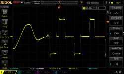
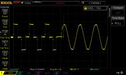
A characteristic feature of offline UPSs is a short break in the power supply to the loads after a power outage. This is related to (usually) relay disconnection of the load from the network, activation of the emergency voltage source and switching the load to a new power source. Similarly, the return to mains voltage requires switching operations using relays. The switching time usually does not exceed 10ms.
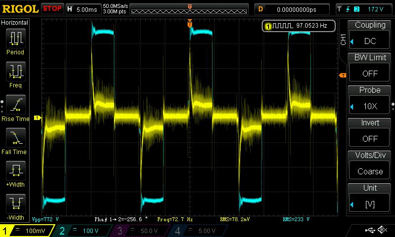
This is how the offline UPS is switched from mains to battery operation and back to mains:
The short-term interruption in the power supply of the loads during switching to battery operation, typical for an offline UPS, should not affect the operation of the connected devices with lower power (due to the energy stored in the "excess capacities" of the power supply systems of these devices). For more powerful devices and critical loads, it is better to use an online UPS. In short: a low-power network switch, CCTV recorder, and even a small NAS or computer should not "notice" a power outage. However, for devices that are critical for the functioning of the company and consume more power, e.g. a disk array, a PoE switch that powers a dozen or even several dozen devices, it is better to use an online UPS. This is a very general rule with exceptions, but you have to start somewhere when choosing an uninterruptible power supply. Offline UPSs usually have a simpler design, lower power and also a lower price than online UPSs. Simple offline UPSs usually do not have the ability to connect external batteries to extend operation after a power outage.
The offline UPS does not convert energy during mains operation (except in AVR mode), resulting in high efficiency. The power input is connected by a relay to the output, while the losses are mainly powering the UPS electronics and charging the battery. To compare the device with the UPS online, you can estimate its efficiency at different powers consumed by the loads. The increase in "efficiency" at higher powers will mainly result from the decreasing share of power for UPS's own needs in the total power drawn from the grid. A very "rough" estimate, but it will give us a comparison with online devices.
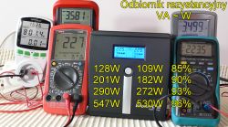
At the input, we estimate the active power using a wattmeter (and we control the apparent power with multimeters to verify that the indications of a not very accurate wattmeter are in the correct order of magnitude). At the output, we measure the apparent power, since the receiver is resistive, we can assume that VA ~ W. The results will of course be different when the battery charger starts working. The estimation was carried out with charged batteries (i.e. typical UPS operating conditions). Anywaywe get an efficiency range of 85-96%, which should come as no surprise when we know how the device works.
The declared power of 600W was taken from the UPS, but in the picture you can see the power consumption of 800W at the input - what happened then?
The UPS reacted properly and after a while turned off the power to the loads. This possibility of momentary overload is very important when, for example, we connect a device with a large value of input capacitance and high current during switching on.
Operation of the AVR system in an offline line-interactive UPS
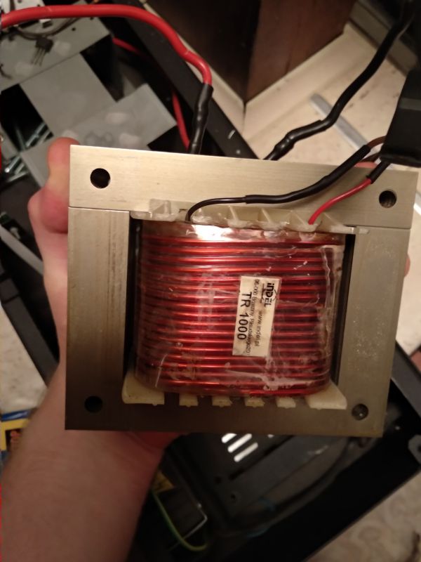
The output voltage regulation system can be compared to an autotransformer connected at the output of the device. Depending on the input voltage, you can add the voltage to the output or subtract it when the input voltage is too high. The added or subtracted voltage during the tests was ~37V.
In the case of the tested device, three operating states with input voltage can be distinguished:
Input voltage 210-255V: input connected to the output via relays.
Input voltage 209-175V: Active AVR output voltage 246-205V.
Input voltage >255V : active AVR system output voltage >218V.
The transition to battery operation takes place at the input voltage
We will look inside both shared devices and compare their internal construction. In the material you will also find videos recorded during tests and after opening the housing of the devices.
Offline line-interactive UPS Green Cell Micropower 1000VA
According to the manufacturer's specification, it is a UPS with an output power of 1000VA / 600W. The energy for emergency operation is stored in two serially connected AGM 12V/7Ah batteries. In UPSs of this class, a single 12V battery is often used. The increased voltage allows you to work with less current discharging the batteries, we also get more Wh. For own needs, the emergency power supply consumes 20-50W (depending on the battery charge level). The design of the device is compact, the UPS is quiet (no forced cooling), but it is worth providing it with good ventilation to, among others extend battery life. The backlit LCD display is very readable and provides information about the operating mode, input and output voltage, battery charge level, power received from the UPS. The device has only one on/off button. Perhaps an additional UPS/battery test button would be useful?


On the back of the UPS there are two types of sockets, which will be especially useful in home applications, where, apart from IEC C-13 plugs, we often meet Schuko plugs. On the rear wall there is an input circuit fuse, a USB connector for communication with the software and a surge protector with an 8P8C (RJ45) connector. In the arrester, pins 1-6 are connected, pins 4-5 are swapped. The construction is based on diodes and varistors. It can be assumed that it is a protector dedicated to FastEthernet and telecommunication devices, e.g. ADSL modems.


Softwareimplements the assumed functions, but in my opinion, the application interface can be slightly refreshed in the future:


Offline UPS practice tests
A characteristic feature of offline UPSs is a short break in the power supply to the loads after a power outage. This is related to (usually) relay disconnection of the load from the network, activation of the emergency voltage source and switching the load to a new power source. Similarly, the return to mains voltage requires switching operations using relays. The switching time usually does not exceed 10ms.
This is how the offline UPS is switched from mains to battery operation and back to mains:


The short-term interruption in the power supply of the loads during switching to battery operation, typical for an offline UPS, should not affect the operation of the connected devices with lower power (due to the energy stored in the "excess capacities" of the power supply systems of these devices). For more powerful devices and critical loads, it is better to use an online UPS. In short: a low-power network switch, CCTV recorder, and even a small NAS or computer should not "notice" a power outage. However, for devices that are critical for the functioning of the company and consume more power, e.g. a disk array, a PoE switch that powers a dozen or even several dozen devices, it is better to use an online UPS. This is a very general rule with exceptions, but you have to start somewhere when choosing an uninterruptible power supply. Offline UPSs usually have a simpler design, lower power and also a lower price than online UPSs. Simple offline UPSs usually do not have the ability to connect external batteries to extend operation after a power outage.
The offline UPS does not convert energy during mains operation (except in AVR mode), resulting in high efficiency. The power input is connected by a relay to the output, while the losses are mainly powering the UPS electronics and charging the battery. To compare the device with the UPS online, you can estimate its efficiency at different powers consumed by the loads. The increase in "efficiency" at higher powers will mainly result from the decreasing share of power for UPS's own needs in the total power drawn from the grid. A very "rough" estimate, but it will give us a comparison with online devices.

At the input, we estimate the active power using a wattmeter (and we control the apparent power with multimeters to verify that the indications of a not very accurate wattmeter are in the correct order of magnitude). At the output, we measure the apparent power, since the receiver is resistive, we can assume that VA ~ W. The results will of course be different when the battery charger starts working. The estimation was carried out with charged batteries (i.e. typical UPS operating conditions). Anywaywe get an efficiency range of 85-96%, which should come as no surprise when we know how the device works.
The declared power of 600W was taken from the UPS, but in the picture you can see the power consumption of 800W at the input - what happened then?
The UPS reacted properly and after a while turned off the power to the loads. This possibility of momentary overload is very important when, for example, we connect a device with a large value of input capacitance and high current during switching on.
Operation of the AVR system in an offline line-interactive UPS
The output voltage regulation system can be compared to an autotransformer connected at the output of the device. Depending on the input voltage, you can add the voltage to the output or subtract it when the input voltage is too high. The added or subtracted voltage during the tests was ~37V.
In the case of the tested device, three operating states with input voltage can be distinguished:
Input voltage 210-255V: input connected to the output via relays.
Input voltage 209-175V: Active AVR output voltage 246-205V.
Input voltage >255V : active AVR system output voltage >218V.
The transition to battery operation takes place at the input voltage
Cool? Ranking DIY


