logo elektroda
logo elektroda
X
logo elektroda

ESP32 Serial Communication Issue with Arduino Mega and PC Application

madiz08 1353 19
ADVERTISEMENT
Treść została przetłumaczona polish » english Zobacz oryginalną wersję tematu
  • #1 18167803
    madiz08
    Level 14  
    Hello
    Trying to make a control for a project:
    https://www.elektroda.pl/rtvforum/topic3613898.html
    In general, yes:
    I have an ESP32 which is the main unit
    There is an Arduino mega which sends data every 2ms via Serial2
    There is also a PC Application which communicates with the ESP32 via Serial
    The problem is that when I press a button on the application, the application sends a command via serial to the ESP32, but sometimes the reading is not correct

    When I didn't use Serial2, everything was ok. When I use Serial2, I find that sometimes the information from the application is cut off. I thought, that there is some independent queuing and storing information from each serial, but here it turns out, that when information from Serial and Serial1 comes simultaneously, the one which comes first is read correctly, and the second one is not.
    How can this problem be solved?

    I am uploading the ESP32 code below, if that would help
    Code: C / C++
    Log in, to see the code


    Added after 4 [minutes]:

    I thought about using a second processor, but it doesn't work
    Do you have a problem with Arduino? Ask question. Visit our forum Arduino.
  • ADVERTISEMENT
  • Helpful post
    #2 18167872
    khoam
    Level 42  
    madiz08 wrote:
    There is an Arduino mega which sends data every 2ms via Serial2.
    There is also a PC Application that communicates with the ESP32 via Serial
    .
    Do you have level converters? The RX inputs on the ESP32 should receive signals in 3V3 logic. This is not clear from the project description.
  • ADVERTISEMENT
  • #3 18167882
    madiz08
    Level 14  


    .
    In the video above you can see what happens when I send text. In the code below:
    Code: C / C++
    Log in, to see the code
    .
    you can see that what comes from the application is supposed to be sent back to it in the same form, but unfortunately this is not the case. Perhaps what seems odd is the use of '@' as the end of the message. It turns out that the application doesn't seem to send '@' or '@', so when I tried to specify the end of the line with either of those characters, I didn't get any string back.

    Added after 3 [minutes]: .

    When I disconnect the data cable from the ArduinoMega, there are no problems, every message from the application comes in the same form as it was sent, but then I don't have the current positions from the encoders

    Added after 3 [minutes]:

    I don't have converters, I'm aware that the ESP32 has different voltages to the Mega, but it's ok with that. The ESP32 downloads data correctly to RX2 with 5V all the time, and does so seamlessly. The app, on the other hand, transmits data over USB.
  • ADVERTISEMENT
  • Helpful post
    #4 18167899
    khoam
    Level 42  
    Try in the above example, immediately after the Serial.println(data) command, issue the Serial.flush() command;

    Added after 47 [seconds]: .

    madiz08 wrote:
    ESP32 downloads correctly on RX2 with 5V all the time and does so without problems.
    .
    This is not known and is certainly not correct.
  • #5 18167943
    madiz08
    Level 14  
    Unfortunately this didn't do anything, I changed the data transfer from Mega every 10ms. In the video below I wanted to show by moving the robot's axes that the positions are sent correctly, although you may never actually know if something won't come wrong
    It's better, but there's no guarantee that a message from the app won't arrive at the same time as a message from Mega. Will definitely order such a converter on Monday
    https://www.youtube.com/watch?v=4IcpJ1bDmdM&feature=youtu.be
    I don't know what's up with the video transfer, I had to put on Youtube

    Added after 1 [hour] 3 [minutes]:

    And yet :( , the transfer from Mega to ESP32 is not ideal. By entering 0.commute.200.150.@ in the serial monitor, I force axis 0 to commute to position 200 at 150. I tested once:
    0.commute.200.150.@
    and back
    0.approach.-200.150.@
    i.e. left at 200 and right at -200
    I noticed that every now and then it stops before the destination point, which it shouldn't, because stopping is getting to the set position. i set up a trap so that the position value is displayed at the time of arrival and i got something different than i should, so it's wrong!
    Could I ask for the name of these converters? I will definitely be ordering something like that on Monday. The reason for adding the Mega as an encoder position reader was that the ESP32 was misreading the pulses from the encoders, but fed either 0V or 5V to the inputs. Maybe if I followed the 3.3V logic the readings would be correct. I will check this tomorrow. Well nothing thanks for diagnosing the problem
  • Helpful post
    #6 18168069
    khoam
    Level 42  
    madiz08 wrote:
    Could I ask for the name of these converters?
    .
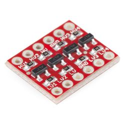
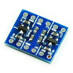
    If in Poland, then under the name "logic state converter", if in China, then "logic level converter" ;) .
    It looks like this, as in the images below. The latter is a "dedicated" one for RX/TX, but both are suitable.

    ESP32 Serial Communication Issue with Arduino Mega and PC Application ESP32 Serial Communication Issue with Arduino Mega and PC Application .

    Added after 51 [minutes]:

    There is one more thing. In the loop() you sequentially read the data via Serial2 from the PC application first, and then the data via Serial from the Mega. As you yourself pointed out, this can result in data being lost from either source. The Arduino HAL on the ESP32 is based on FreeRTOS, so you can take advantage of multitasking. In the simplest terms, you could define a separate task for reading data from the Mega with a higher priority than the loop(), that is, higher than 1.

    I provide links with simple examples below:
    https://techtutorialsx.com/2017/05/06/esp32-arduino-creating-a-task/
    https://github.com/espressif/arduino-esp32/bl...ibraries/ESP32/examples/FreeRTOS/FreeRTOS.ino
  • #7 18168763
    madiz08
    Level 14  
    Very interesting topic, I tried even before in a similar way to flip the reading from Mega to Core 0, but I didn't succeed. I added something like this according to the recommendations from the link
    Code: C / C++
    Log in, to see the code
    .
    The downside is that in these shuffles you have to add delay(>=1), because if this is to be executed continuously it has to be in the fro() petla, is that right?
    In addition, I have introduced a condition that if the read position from megi, deviates by 10 positions from the previous transfer, this read is to be ignored. When it comes to readings from megi there is a big improvement, this priority I set to 2.
    The reading from the app is also important, see if you can the video below
    https://youtu.be/p85hkcGzs8Q
    By pressing a particular button, I simply send the information by serial. If at the same time the Mega is transmitting data, the data from the app is not received in its entirety
    At time 1:20, you can see as I press the button the application sends 3 lines:
    serialPort1.WriteLine("0.access.200.100.@");
    serialPort1.WriteLine("1.commute.200.100.@");
    serialPort1.WriteLine("2.commute.-200.90.@");
    .
    As you can see the first line of code doesn't read correctly because axis[0] didn't move, it was only when I clicked the button again that the 3 axes were in the 200 positions.
    How would it be possible to make it so that the data from the application is read by the second processor, i.e. Core0?
  • #8 18168776
    khoam
    Level 42  
    madiz08 wrote:
    Minus you have to add delay(>=1) in these shuffles, because if this is going to be executed continuously it has to be in the fro() petli, is that right?
    .
    Yes, you even need to add delay() to specify the time interval of the task that it should call every. This is not a downside, during this delay() other tasks will be allowed to run, including the loop(), so it should be rather longer than 1ms . Yes, as I have already written the Arduino HAL in ESP32 is RTOS based, so delay() in a given task does not hold up the execution of other FreeRTOS tasks.

    madiz08 wrote:
    How would you make it so that data from the application is read by the second processor, i.e. Core0?
    .
    And how do you create a task for reading data from the Mega? You haven't posted this piece of code.

    Added after 2 [minutes]:

    madiz08 wrote:
    Reading from the app is also important, see if you can for the video below
    .
    Then define another task for this read with a priority higher than loop(), but lower or the same as for the Mega read task.
  • #9 18168974
    madiz08
    Level 14  
    Aha, that's how it works! What I have posted is just reading from the Mega via serial2. The app communicates via USB, so it must be Serial. I'll get around to adding the other thread soon and let you know
  • #10 18168989
    khoam
    Level 42  
    madiz08 wrote:
    What I have posted is just the reading from the Mega via serial2.
    .
    Yes, you posted the callback function definition taskOne() for the task declared as? What you have in setup() ;) .
  • #11 18169019
    madiz08
    Level 14  
    Super :) , I let the robot go into a loop and after more than 40 smooth trajectories I stopped. Thanks a lot for your help. Really strong is this ESP32
  • ADVERTISEMENT
  • Helpful post
    #13 18176218
    krzbor
    Level 27  
    Do not connect 5v and 3.3V devices - in any case not directly. The uP inputs are protected by diodes. If you connect a 5v signal to the 3.3V circuit, you will of course force a high state, but a considerable current will flow through the protection diode when 4v is exceeded. The fact that something won't burn up is only due to the fact that the current is limited by the transmitting circuit (here the Mega). Therefore, if you don't want converters, you can:
    - transmit from a 3.3V to 5V circuit - connect directly (mostly works, as the 3.3V will already be recognised as a high state). I write mostly, because the catalogue notes usually indicate a slightly higher voltage for "1" in 5V circuits
    - Transmitting from the 5V circuit to 3.3V - use a divider (this is the best solution) or connect via a resistor of approx. 2.2k. Using a resistor uses a protection diode, but simply limits the current flowing through it.
    I think the 'poorest' version (1 resistor) will not drain the budget, and certainly the ESP will not be damaged.
  • #14 18180363
    madiz08
    Level 14  
    I've recently stopped with the topic, due to damage to the heater from the 3D printer (I'm waiting for a new shipment from China), but I wanted to check the heating of the axis 2 motors with increased current on the axis motors.
    https://youtu.be/jlWJpc1fdXc
    After the second hour, the third axis started to box, it didn't stop at the target point just drove over it and stopped at its end position (mechanically it couldn't go any further and the stepper motors started to box)
    I saw that a piece of code could be the cause of this:
    Code: C / C++
    Log in, to see the code
    .
    I get a reading from the Mega every 5ms, if it reads wrong a couple of times, that is, the reading is out of the +15 or -15 position range from the previous reading then the motor will actually travel those 15 positions and even if it sends the correct position it still won't be overwritten in esp32.

    I went back to rigidly assigning what I read
    Code: C / C++
    Log in, to see the code
    .
    I did this for each of the three axes and strange things started to happen, as if the robot didn't know what to do.
    The code for sending data from the Mega looks like this:
    Code: C / C++
    Log in, to see the code
    .

    And the current reception on the ESP32 is implemented by Core0 and looks like this:
    Code: C / C++
    Log in, to see the code
    .
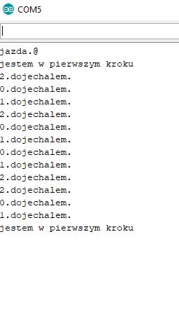
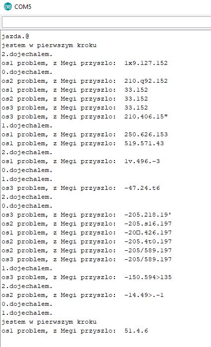
    I've set up a trap that if the new axis position is out of the +-15 range from the previous reading, so that it displays to me what the ESP32 has received from the Mega, and this is where the problems come out:
    When the stepper motors are not engaged and I manually move the axes there is no problem at all
    ESP32 Serial Communication Issue with Arduino Mega and PC Application .
    When the trajectory is called by typing "drive.@" the robot starts to arrive at its target positions, when it arrives it sends "no_axis.arrived". In the above picture I arrived at the target points by manually moving the axes and zero problem. I then attached the stepper motors and attached the trajectories:
    ESP32 Serial Communication Issue with Arduino Mega and PC Application .

    It doesn't matter if I run the TX signal from the Mega through a logic state converter, directly or with a 2k2 resistor. There is always a similar number of errors, sometimes a little more, sometimes a little less. Perhaps surprisingly there are a few more errors when using the converter,
    It is already clear that this is caused by interference, if nothing bad happens without steppers.

    ESP32 Serial Communication Issue with Arduino Mega and PC Application
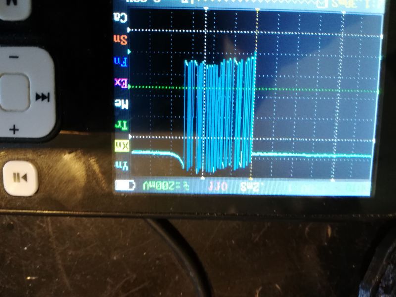
    This is what the data looks like on the oscilloscope this with a 2k2 resistor on the transmission line (which is now)

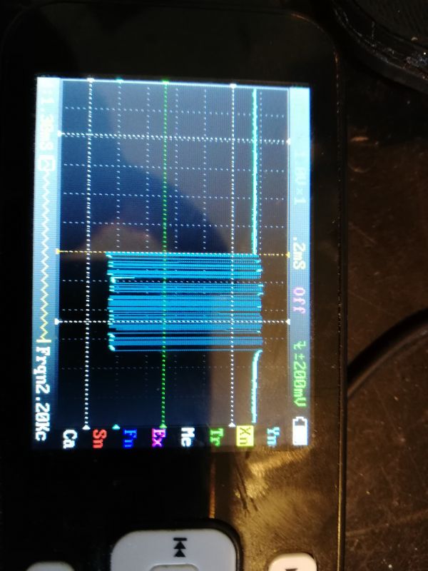
    ESP32 Serial Communication Issue with Arduino Mega and PC Application
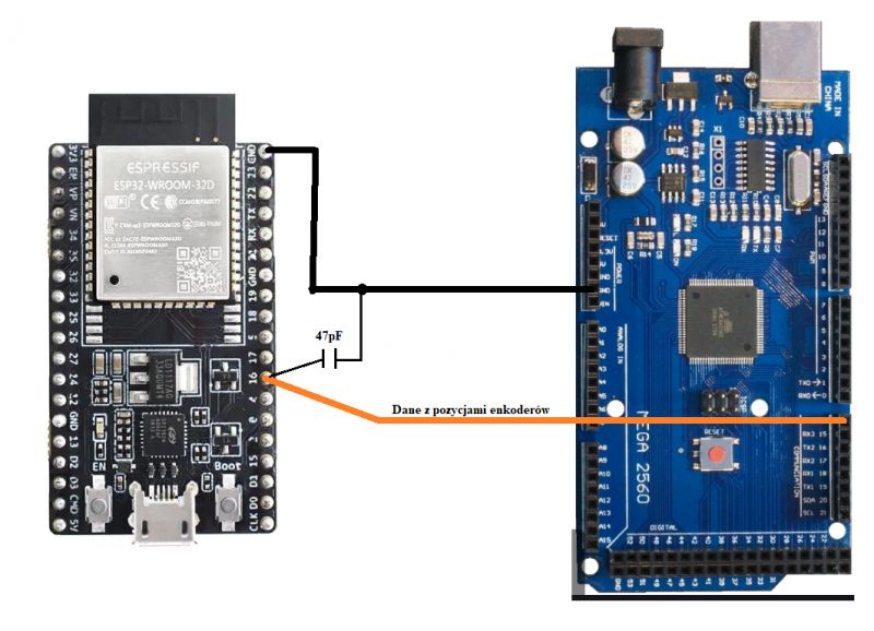
    and yes after adding a 47pF capacitor the TX line of the Megi and GND. After zooming in, which I don't have in the picture, there is a really nice signal, but still wrong readings are coming from Megi.
    ESP32 Serial Communication Issue with Arduino Mega and PC Application .
    Do you have any ideas how such connections could still be 'sub-filtered' to avoid erroneous data transfer?
    As for the encoder position readings themselves via the Mega, it is 100% fine here. As you can see in one of the pictures above.
  • #15 18180672
    khoam
    Level 42  
    madiz08 wrote:
    A current reception in ESP32 is implemented by Core0 and looks like this:
    .
    If you call this task every 4 ms, and in it you call the Serial.print() function, then it is not really known how often this task actually calls itself. Dumping the data content to Serial (USB port) is a bit time consuming.
    The same comment applies to the wait loop in this task:
    Code: C / C++
    Log in, to see the code
    .
    You don't use such a structure in tasks that are supposed to be called cyclically at short intervals, because you don't really know what the final value of this interval will be and how it will change in subsequent iterations. Such waiting loops stop the execution of a particular task, but of course do not stop the operation of other FreeRTOS tasks.
    I don't know to what extent this might have an impact on the problem at hand, but the algorithm of the function codeForTask1() is rather something that needs to be improved.
  • #16 18180861
    madiz08
    Level 14  
    I think it's definitely the fault of the interference itself, but as much as I'd like to write the code correctly, especially as I'm not a good programmer. Regarding the interference itself, I'll try to get a piece of shielded cable from work tomorrow and see if there is any difference.
    Regarding the data exchange code itself in processor 0, would that be a better solution?
    Code: C / C++
    Log in, to see the code
    .
    I uploaded something like this still with a safety feature that if there is a bad reading 3 times in a row then stop the robot and the same thing after about 35 minutes of repeating the trajectory the robot stopped. When I trigger the trajectory execution again the robot drives from where it stopped, it has perfectly reached the target position, hence my assumption that the encoder reading is 100% correct.

    Added after 9 [minutes]: .

    Also looking at the oscilloscope, I can see a data transfer on it every 5ms or so also seems fine.
  • #17 18180901
    khoam
    Level 42  
    madiz08 wrote:
    I think the interference itself is definitely to blame
    .
    There's no denying that 'standard' Mega or ESP32 boards are not designed with interference immunity in mind. Looking at the image in this thread , it seems to me that you should connect the two UARTs directly with a twisted pair (can be unshielded) and see if interference is reduced.

    madiz08 wrote:
    For the code itself
    .
    Comment out the Serial.print() calls in the codeForTask1() function for now. You won't get a preview in the serial port monitor, but we'll see if things improve. What speed do you have set in Serial.begin() in the code for ESP32?
  • #18 18181842
    madiz08
    Level 14  
    Well I will try to test it today after work and will let you know. As for the baud rate it is set to 115200.
  • #19 18182683
    khoam
    Level 42  
    madiz08 wrote:
    When it comes to baud rate it is set to 115200.
    .
    In the case of the ESP32 you can set Serial.begin(500000). Of course, in the serial port monitor you also need to change it to 500,000.
  • #20 18183612
    madiz08
    Level 14  
    Yet it was interference, a twisted pair without a screen did not help. I unbolted the profibus plug from the training PLC. The profibus cable has two wires and a shield, which I connected to ground on one side and the other, and for 30 minutes zero erroneous messages. You can immediately see that acceleration and braking are smoother. In my spare time I will still test how the system behaves at higher transmission speeds. Actually, it's interesting, because I remember that when I reduced the speed to 9600 (checking on the oscilloscope, of course, that there are sufficient gaps between data packets) there was much more interference.
    Oh well, many thanks again for your help, I am now waiting for a new heater for the 3D printer I will try to add the other axes

Topic summary

The discussion revolves around a serial communication issue involving an ESP32, an Arduino Mega, and a PC application. The user experiences data loss when commands are sent simultaneously from the PC application and the Arduino Mega via Serial2. Suggestions include using level converters for voltage compatibility, implementing multitasking in the ESP32 to prioritize data reading from the Mega, and optimizing the code to avoid blocking operations. The user also experimented with different baud rates and cable types to reduce interference, ultimately finding that using a shielded cable improved communication reliability.
Summary generated by the language model.
ADVERTISEMENT