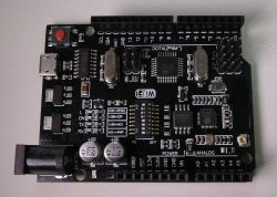
Arduino UNO + ESP8266 module on one board contains UNO based on ATmega328 and WiFi module based on ESP8266. The cost of the module on auction portals is ~ $ 7 Link . The module can be powered from a micro USB socket or DC 7-12V connector. Communication with the modules takes place via the USB UART converter based on the CH340 chip. Arduino UNO works with 5V, while ESP8266 is 3.3V. The ESP8266 pins are available on an additional connector, similarly the ISP connector allows you to program ATmega328 without bootloader:
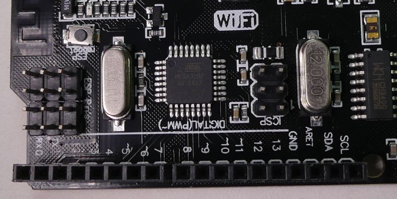
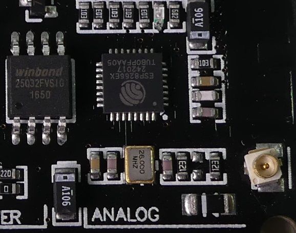
Looking at the PCB, you can see some assembly inaccuracies, e.g. the uFL connector of an external WiFi antenna. As standard, we can use a WiFi antenna in the form of a path on a printed circuit board.
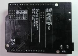
Description of the ESP8266 pins is on the other side of the board:
When connecting the ESP8266 and UNO pins, remember about different voltage levels, similarly when connecting the peripherals.
After setting the switches ESP8266 and ATmega328 can communicate using UART, similarly setting the jumpers allows you to connect the UART USB converter with the selected module for programming.
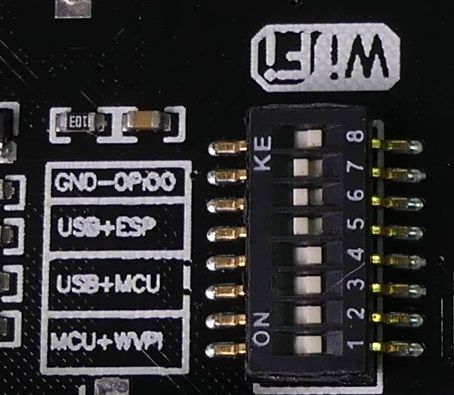
Connection of modules via UART - DIP 1 and 2 ON
USB UART connection with ATmega328 - DIP 3 and 4 ON
USB UART connection with ESP8266 - DIP 5 and 6 ON
USB UART connection with ESP8266 in programming mode (GPIO0-GND) - DIP 5 and 6 and 7 ON
Do you think such a combination of ATmega328 with ESP8266 on one board makes sense?
Arduino UNO can extend the capabilities of ESP8266, e.g. in terms of the number of I / O, ADC, PWM,
offload / buffering for ESP during measurements or communication with peripherals, increasing the energy efficiency of ESP8266 similar to here: Link
It is inconvenient to switch miniature switches to change modes. It should be remembered about the difference in voltage levels between the pins of the ESP module and the Arduino.
Below is information on how to integrate both parts of the module with Arduino, and send data to Thingspeak:
ESP8266 WIFI boot, start from IoT, Blynk, Thingspeak
Arduino Uno first run. DHT22, BMP180, FFT LED RGB.
A practical example of using the module ,
data transmission from 6 ADC Arduno Uno channels to Thingspeak via WiFi ESP8266:
Code for Arduino UNO ,
for the duration of programming, switch to the "ON" position USB + MCU (switches 3 and 4),
for the time of cooperation between Arduino UNO and ESP8266, select the MCU + ESP (1,2) option.
Code for ESP8266 ,
for the programming time, set the switches 5,6,7 in the "ON" position,
for the duration of operation, set the switches 1,2 in the "ON" position,
if we want to observe messages on the serial terminal, in the "ON" position, set the switches 5,6 or 1,2,5,6.
In the code, as described, we put the SSID of our WiFi network and password,
and also thingspeak api key and our channel number.
[syntax=c]//programing USB+ESP GND-GPIO0 on (5,6,7)
//runing MCU+ESP (1,2)
//debug ESP+USB on (5,6) or (1,2+5,6)
//serial 9600bps
//send data from ADC to thingpseak
#include
#include
#define UART_SPEED 9600
#define ADC_CH 5
//Credential and parameters for WiFi
const char* ssid = "SSID WiFi";
const char* password = "WiFipassword";
//Parameters for thingspeak
const char * apiKey = "apiKeyForYourthingspeak";
unsigned long myChannelNumber = 123456;
// api.thingspeak.com
const char* server = "api.thingspeak.com";
WiFiClient client;
void setup() {
byte n = 0;
byte mac[6];
Serial.begin(UART_SPEED);
//Connecting to WiFi
Serial.print("Connecting to WiFi SSID: ");
Serial.print(ssid);
Serial.println("");
WiFi.begin(ssid, password);
WiFi.macAddress(mac);
for (n; n < 6; n++) {
Serial.print(mac[n], HEX);
if (n < 5)
Serial.print(":");
else
Serial.println("");
}
n = 0;
while (WiFi.status() != WL_CONNECTED) {
delay(1000);
Serial.print(".");
if (n > 60) {
ESP.restart();
Serial.println("restart ");
}
n++;
}
Serial.println("");
Serial.println("WiFi connection OK");
ThingSpeak.begin(client);
delay(10000);
}
void loop() {
String in_buff;
int adc_val;
float voltage;
#define ADC_MAX 1023
#define V_REF 5.0
for (byte n = 0; n

Looking at the PCB, you can see some assembly inaccuracies, e.g. the uFL connector of an external WiFi antenna. As standard, we can use a WiFi antenna in the form of a path on a printed circuit board.

Description of the ESP8266 pins is on the other side of the board:

When connecting the ESP8266 and UNO pins, remember about different voltage levels, similarly when connecting the peripherals.
After setting the switches ESP8266 and ATmega328 can communicate using UART, similarly setting the jumpers allows you to connect the UART USB converter with the selected module for programming.

Connection of modules via UART - DIP 1 and 2 ON
USB UART connection with ATmega328 - DIP 3 and 4 ON
USB UART connection with ESP8266 - DIP 5 and 6 ON
USB UART connection with ESP8266 in programming mode (GPIO0-GND) - DIP 5 and 6 and 7 ON
Do you think such a combination of ATmega328 with ESP8266 on one board makes sense?
Arduino UNO can extend the capabilities of ESP8266, e.g. in terms of the number of I / O, ADC, PWM,
offload / buffering for ESP during measurements or communication with peripherals, increasing the energy efficiency of ESP8266 similar to here: Link
It is inconvenient to switch miniature switches to change modes. It should be remembered about the difference in voltage levels between the pins of the ESP module and the Arduino.
Below is information on how to integrate both parts of the module with Arduino, and send data to Thingspeak:
ESP8266 WIFI boot, start from IoT, Blynk, Thingspeak
Arduino Uno first run. DHT22, BMP180, FFT LED RGB.
A practical example of using the module ,
data transmission from 6 ADC Arduno Uno channels to Thingspeak via WiFi ESP8266:
Code for Arduino UNO ,
for the duration of programming, switch to the "ON" position USB + MCU (switches 3 and 4),
for the time of cooperation between Arduino UNO and ESP8266, select the MCU + ESP (1,2) option.
Code: C / C++
Code for ESP8266 ,
for the programming time, set the switches 5,6,7 in the "ON" position,
for the duration of operation, set the switches 1,2 in the "ON" position,
if we want to observe messages on the serial terminal, in the "ON" position, set the switches 5,6 or 1,2,5,6.
In the code, as described, we put the SSID of our WiFi network and password,
and also thingspeak api key and our channel number.
[syntax=c]//programing USB+ESP GND-GPIO0 on (5,6,7)
//runing MCU+ESP (1,2)
//debug ESP+USB on (5,6) or (1,2+5,6)
//serial 9600bps
//send data from ADC to thingpseak
#include
#include
#define UART_SPEED 9600
#define ADC_CH 5
//Credential and parameters for WiFi
const char* ssid = "SSID WiFi";
const char* password = "WiFipassword";
//Parameters for thingspeak
const char * apiKey = "apiKeyForYourthingspeak";
unsigned long myChannelNumber = 123456;
// api.thingspeak.com
const char* server = "api.thingspeak.com";
WiFiClient client;
void setup() {
byte n = 0;
byte mac[6];
Serial.begin(UART_SPEED);
//Connecting to WiFi
Serial.print("Connecting to WiFi SSID: ");
Serial.print(ssid);
Serial.println("");
WiFi.begin(ssid, password);
WiFi.macAddress(mac);
for (n; n < 6; n++) {
Serial.print(mac[n], HEX);
if (n < 5)
Serial.print(":");
else
Serial.println("");
}
n = 0;
while (WiFi.status() != WL_CONNECTED) {
delay(1000);
Serial.print(".");
if (n > 60) {
ESP.restart();
Serial.println("restart ");
}
n++;
}
Serial.println("");
Serial.println("WiFi connection OK");
ThingSpeak.begin(client);
delay(10000);
}
void loop() {
String in_buff;
int adc_val;
float voltage;
#define ADC_MAX 1023
#define V_REF 5.0
for (byte n = 0; n
Cool? Ranking DIY


