FAQ
TL;DR: For NodeMCU+RS485, wire DI→TX0, RO→RX0, and control DE/RE via callbacks. ESP8266 has 2 UARTs; "Serial1 cannot receive data, only send it." Use UART0 for RS485 and keep USB or Wi‑Fi logging. For makers wiring MAX485‑type modules to ESP8266 NodeMCU with ModbusMaster. [Elektroda, khoam, post #18282384]
Quick Facts
- Wiring: DI→MCU TX, RO→MCU RX; receive‑only: hold DE low and /RE low; terminate bus with 120 Ω at both ends. [“MAX485 datasheet”]
- ESP8266 UARTs: UART0 TX0/RX0 on GPIO1/3 (USB); Serial.swap→GPIO15/13; UART1 TX‑only on GPIO2. [“Arduino core for ESP8266 — Serial”]
- ModbusMaster usage: node.begin(slaveId, Serial); preTransmission/postTransmission toggle RE/DE via GPIO for half‑duplex. [“ModbusMaster RS485_HalfDuplex example”]
- Voltage: ESP8266 is 3.3 V logic; inputs are not 5 V tolerant—use 3.3 V transceivers or level shifting. [“ESP8266EX Datasheet”]
- Register math example: two 16‑bit registers → one 32‑bit value, then divide by 10 in glueFloat(). [Elektroda, khoam, post #18284720]
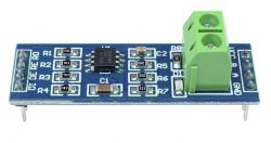
How do I connect DI and RO from an RS485 converter to ESP8266 NodeMCU?
Connect DI to NodeMCU TX0 (U0TXD) and RO to RX0 (U0RXD). This pairs the converter’s TTL side with Serial on the ESP8266. Then manage direction using DE/RE as described below. [Elektroda, khoam, post #18262228]
I only want to receive—how should I wire DE/RE?
On MAX485‑type chips, enable receive and disable transmit. Set DE LOW and /RE LOW. If your board ties DE and /RE together, pull the combined pin LOW. This keeps the driver off and the receiver on. [“MAX485 datasheet”]
Do preTransmission and postTransmission callbacks handle RS485 direction for me?
Yes. Register these callbacks in ModbusMaster to drive your RE/DE GPIO before and after each Modbus frame. The example shows how and lets you choose any pin. "DE/RE support is included." [Elektroda, khoam, post #18262535]
What does publishFloat("Ppv", glueFloat(...)) actually do?
It formats the float with one decimal, builds a topic like inverter/Ppv, and publishes retained to MQTT. The function fills topic_char and value_char buffers and calls client.publish(topic_char, value_char, true). [Elektroda, khoam, post #18262583]
Does publishFloat send to topic_char and value_char?
Yes. The function converts the float to value_char, builds topic_char, and passes both to client.publish as payload and topic. [Elektroda, khoam, post #18262583]
Can I run RS485 on UART1 and keep USB logging on UART0?
Not for receiving. ESP8266 has two UARTs, but UART1 is TX‑only on GPIO2. "Serial1 cannot receive data, only send it." Use UART0 for RS485 and log via Wi‑Fi or a second USB‑serial. [Elektroda, khoam, post #18282384]
What exactly does Serial.swap() change on ESP8266?
Serial.swap() remaps UART0 from GPIO1/3 to GPIO15/13. The onboard USB interface then stops, since it connects to GPIO1/3. Use swap only if you relocate your USB‑serial to GPIO15/13. [Elektroda, khoam, post #18282384]
How do I set the Modbus slave ID with ModbusMaster?
Call node.begin(slaveId, Serial). Example: node.begin(1, Serial) targets slave ID 1 on UART0. Ensure the slave ID matches your device configuration. [Elektroda, robo1973, post #18262514]
How do I combine two Modbus registers into a 32‑bit value?
Use glueFloat(d1, d0): compute (d1 << 16) + d0, then divide by 10 for scaling. On ESP8266, unsigned int is 32‑bit, so a single expression works. Two 16‑bit registers represent one 32‑bit number. [Elektroda, khoam, post #18284720]
d0 = 10 returns 1.0 — what does d1 change?
d1 is the high 16‑bit word. With d1 = 0, the function returns d0/10, so 10 becomes 1.0. If d1 changes but results do not, verify response buffer indexes and the device’s word order. [Elektroda, khoam, post #18284720]
How do I set up DE/RE control with ModbusMaster (quick steps)?
- Choose a GPIO for RE/DE and set it as OUTPUT.
- Write preTransmission() to set RE/DE HIGH; write postTransmission() to set it LOW.
- Register callbacks with node.preTransmission(...) and node.postTransmission(...), then call node.read/write functions. [“ModbusMaster RS485_HalfDuplex example”]
Which pins are UART0 and UART1 on NodeMCU?
UART0: TX0=GPIO1, RX0=GPIO3 (USB). With Serial.swap, TX0=GPIO15 and RX0=GPIO13. UART1: TX1=GPIO2 only; it has no RX. [Elektroda, khoam, post #18282384]
Is ESP8266 5 V tolerant on RX when my RO outputs 5 V?
No. ESP8266 inputs are 3.3 V only. Use a 3.3 V‑compatible RS485 transceiver or level‑shift RO to 3.3 V to protect RX0. [“ESP8266EX Datasheet”]
How should I terminate an RS485 bus for reliable Modbus?
Place a 120 Ω resistor across A and B at each end of the cable. Add bias resistors if needed per the transceiver’s recommendations. Keep stubs short to reduce reflections. [“MAX485 datasheet”]


