Good morning,
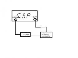
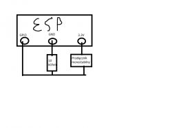
I'm using the ESP32 DevKit V1 board, when reading the input voltage from the analogue pins (GPI: 34,35,36,39), there is some crosstalk and even though the wire is "hanging in the air" or plugged into the prototyping board, out of nowhere, the voltage appears long enough that 'digitalRead()' perceives it as high, and holds above 100ms, I know this because I added an additional instruction to check the status after 100ms. The problem occurs despite a 1 kOhm resistor being soldered in. I don't know how to solve this. Anyone know perhaps how to fix it?
I would also add that pinMode set to INPUT because INPUT_PULLUP gave even worse results and the voltage appeared more often. Previously (without the resistor) all I had to do was hold a wire connected to the input in one hand and a 3.3V wire in the other hand and the voltage was already high enough. for the program to read it as a high state.
I would be forgetting... my observations showed that when, for example, I have a meter plugged into the circuit for 5 minutes (minus of the meter to any GND, and plus anywhere in the circuit - e.g. at the resistor leg), crosstalk does not appear at all. On the other hand, if I briefly unplug the meter, they already occur. Could this suggest that the resistance of the meter "kills" the crosstalk and it is enough to plug in a larger resistor?
Thank you very much for taking the time to read and I hope for a quick reply .
.
I'm using the ESP32 DevKit V1 board, when reading the input voltage from the analogue pins (GPI: 34,35,36,39), there is some crosstalk and even though the wire is "hanging in the air" or plugged into the prototyping board, out of nowhere, the voltage appears long enough that 'digitalRead()' perceives it as high, and holds above 100ms, I know this because I added an additional instruction to check the status after 100ms. The problem occurs despite a 1 kOhm resistor being soldered in. I don't know how to solve this. Anyone know perhaps how to fix it?
I would also add that pinMode set to INPUT because INPUT_PULLUP gave even worse results and the voltage appeared more often. Previously (without the resistor) all I had to do was hold a wire connected to the input in one hand and a 3.3V wire in the other hand and the voltage was already high enough. for the program to read it as a high state.
I would be forgetting... my observations showed that when, for example, I have a meter plugged into the circuit for 5 minutes (minus of the meter to any GND, and plus anywhere in the circuit - e.g. at the resistor leg), crosstalk does not appear at all. On the other hand, if I briefly unplug the meter, they already occur. Could this suggest that the resistance of the meter "kills" the crosstalk and it is enough to plug in a larger resistor?
Thank you very much for taking the time to read and I hope for a quick reply


