logo elektroda
logo elektroda
X
logo elektroda

V and A led meter modification on HC32F003 chip (4 bit, 0-100V, 0-10A)

wsxcde 12597 20
ADVERTISEMENT
Treść została przetłumaczona polish » english Zobacz oryginalną wersję tematu
  • V and A led meter modification on HC32F003 chip (4 bit, 0-100V, 0-10A)

    Hello all.
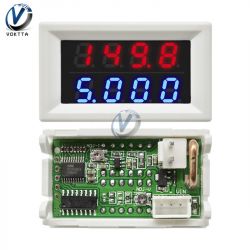
    Some time ago I bought a LED current and voltage meter (4 bit, 0-100V, 0-10A) on the Chinese website. According to the description, it was to provide values with a frequency of 3 times per second. It turned out differently, i.e. he gave them less than once per second, which was unacceptable for my applications.
    The meter is built on the HC32F003 processor. On Chinese websites I found full documentation, SDK and utilities for this processor. I decided to play with him.
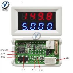
    Attempting to connect with the SWD connector has failed. This should have been done using the serial port. It worked, but the flash could not be read - it was secure. So one thing remained - delete the flash and write the software from scratch, which I also did. By the way, I modified the circuit to measure 0-30V. Wiring diagram:
    V and A led meter modification on HC32F003 chip (4 bit, 0-100V, 0-10A)

    What difficulties did I encounter? A dedicated program did not detect my processor on any USB adapter - serial (I tried on PL2303 and CH340). The FlyMcu program detected the PL2303 chip, but I can't remember why I didn't use it to delete the chip (it didn't allow it?). Eventually, I deleted flash on a Linux computer with a Python program. Now I had full access to the CPU. I programmed and debugged it through the already active SWD port using J-Link (how to make a J-Link adapter with Blue Pill can be found in the network).
    As a result of my scribble (I am not a programmer) I have a meter that gives values very quickly and does it more accurately than on the original software. The measurement frequency can be modified by changing the byte in the flash.bin file under the offset 0xbee (in the range 1-255).
    Included software and flash batch.

    Cool? Ranking DIY
    About Author
    wsxcde
    Level 12  
    Offline 
    wsxcde wrote 30 posts with rating 85, helped 2 times. Been with us since 2005 year.
  • ADVERTISEMENT
  • #2 18773004
    khoam
    Level 42  
    Bravo for this reverse engineering :) Did a colleague check the "linearity" of the voltage measurement in the new 0-30V range?
  • #3 18773120
    metalMANiu
    Level 21  
    Congratulations and I appreciate you sharing your work ?
  • ADVERTISEMENT
  • #4 18773332
    wsxcde
    Level 12  
    The measurement is calibrated for the one I have and it gives the correct values throughout the voltage range (it was not possible to set it in the original software). I have one copy of the meter and I do not know how exactly it will be for others.
  • #5 18773820
    RomanWorkshop
    Level 14  
    Where did "4-bit" in the topic name come from? The HC32F003 microcontroller is 32-bit (ARM Cortex-M0 + core) and has an accurate 12-bit ADC (SAR) converter.
  • #6 18774067
    piotr_go
    DIY electronics designer
    RomanWorkshop wrote:
    Where did "4-bit" in the topic name come from?

    The Chinese call this 4ro digital displays.
    Why? I have no idea.
  • #7 18774108
    wsxcde
    Level 12  
    Exactly, under this name you can search for it on Chinese sites.
  • #8 18774714
    Anonymous
    Level 1  
  • #9 18776651
    Duch__
    Level 31  
    Does RS read something in the original software?
  • #10 18777393
    wsxcde
    Level 12  
    The point is, does soft send something via RS? No, the serial port pins are used for other functions.
  • ADVERTISEMENT
  • #11 18778510
    Anonymous
    Level 1  
  • ADVERTISEMENT
  • #12 18778668
    wsxcde
    Level 12  
    It is similar in my program - at 10 A, horizontal lines will appear. You would have to modify the system (voltage amplification from the measuring resistance) or supply it with 5 V (i.e. also modify it) and change the program.
  • #13 18779036
    Anonymous
    Level 1  
  • #14 18779620
    wsxcde
    Level 12  
    Even those that should show up to 20 A go out? You have a soft attached, which will turn off at 20 A. Anyway, the ADC will saturate earlier, but I think that 12 A will show. The current is given with two decimal places.
  • #15 18780672
    Anonymous
    Level 1  
  • #16 18801210
    ElectroTom
    Level 25  
    How about the accuracy of these measures?
  • #17 18811377
    wsxcde
    Level 12  
    After calibration, it is ok. Unfortunately, the diagram does not allow for the solutions recommended by the manufacturer to increase the accuracy of measurements.
  • #18 19629324
    AlexSt
    Level 2  
    Hi wsxcde,
    Thank you very much for the arcticle and files!
    Can I ask you some questions?

    I need to do the similar things with another device based on this HC32F003 MCU. With your python script I was able to unlock MCU`s flash and with attached flasher - to read and write flash as well.
    You said that you are able to debug it via SWD and JLink. I tried to flash a bluepill with JLink fw and install Segger JLink software (in ubuntu). But unfortunately it doesn't know anything about this chip. The same is with STLink. Can you say few words how you managed to connect JLink to this MCU?
    Which development SW did you use to develop a firmware for this MCU? I found SDK only for Keil/EWW, but I cannot use none of them...
  • #19 19777878
    wsxcde
    Level 12  
    Hi AlexSt.

    I was a little bit out here and didn't notice this post.
    If it is still valid, I will try to help.
  • #20 19780761
    AlexSt
    Level 2  
    Hi wsxcde,

    Currently I solved the issue by replacing the chip by STM8L103 which is pin-to-pin compatible, and wrote a firmware.
    But I think, any details may be very helpful to anyone who tries to program HC32 chips.
  • #21 19781594
    wsxcde
    Level 12  
    I used the IAR. The CPU SDK is available e.g. here:
    https://github.com/yanjainxiong/HDMCU_ZLG/tree/master/HC32F003_SDK
    There are configuration files for the IDE, sample programs, full pinout and processor documentation.
    I connected to the system via SWD (pinout in the documentation, in the photo these are the 5 holes vertically on the left side of the board).

    How to make a J-Link adapter, how to connect? I don't know, he can search for:
    ?????? ?? BluePill ??????????? / ???????? JLink OB-STM32F103
    Official documentation of the J-Link adapter:
    https://www.segger.com/downloads/jlink/UM08023_JLinkOBSTM32F103.pdf

Topic summary

A user modified a LED current and voltage meter based on the HC32F003 microcontroller, originally designed for 0-100V and 0-10A measurements, to improve its performance, which was initially below the expected frequency of 3 readings per second. The user successfully deleted the original firmware and rewrote it, calibrating the meter for a 0-30V range. Discussions included the accuracy of measurements, issues with current readings exceeding 10A, and the potential for further modifications to increase the current range. Other users contributed insights on the microcontroller's specifications, calibration methods, and alternative solutions for programming the device.
Summary generated by the language model.
ADVERTISEMENT