logo elektroda
logo elektroda
X
logo elektroda

Zigbee Lighting Control with Tuya Relays: Stair Switch & Wall Remote Setup

ksar88 2082 5
ADVERTISEMENT
Treść została przetłumaczona polish » english Zobacz oryginalną wersję tematu
  • #1 18922483
    ksar88
    Level 7  
    Hi,

    I would like to install in-duct relays to control lighting in my flat. Below is a link to the relays:

    https://allegro.pl/oferta/przekaznik-dopuszkowy-1ob-zigbee-tuya-dziala-bez-n-9575645567

    https://allegro.pl/oferta/przekaznik-dopuszkowy-1-kanal-zigbee-tuya-ln-9635078646

    I am interested in whether it is possible to control the set: 2x stair switch + cross switch (I can get rid of the cross switch (short out) in favour of a wall remote control).
    I was told at the shop that this can be done at the application level - not too sure how.
    In the first connector I have L and N, in the second the output for the lamp.
    If this is not possible, I will be forced to remove the fader in favour of a single switch + wall remote.
  • ADVERTISEMENT
  • #2 18924227
    sk1977

    IT specialist
    Be more precise - if you have a standard installation of 2x staircase + 1x crossover then you don't have N at any of the switches - see the diagram: https://www.elektroda.pl/rtvforum/topic2133374.html#10131810.
    Is this how your installation looks like?
    In the case of the relays from the links you should provide them with a constant power supply (versions without N via a bulb or capacitor), which can be a problem with stair/cross connectors.
    How many lamps do you have and how controlled and how would you like it to work.
    Helpful post? Buy me a coffee.
  • ADVERTISEMENT
  • #3 18924258
    ksar88
    Level 7  
    1. the N is shorted back from the lamps in the box, it is not connected to any switch.
    2. there are two downlights to be controlled by one button
    3. i would like to leave at least two stair switches, in place of the cross switch i can give a wall remote.
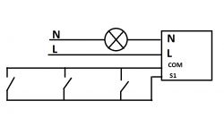
    4. the guy from the wholesaler said that in order to do this, the switches need to be connected as single switches and this can be done systemically, through an app. Unfortunately I don't really know how to program this. As far as the connections are concerned, the only thing that came to my mind was something like this. (The cross-over at the moment is short-circuited, illustrative drawing).
    5. however, if this is not possible, I will opt for switches with relays (to unify the appearance of all the switches in the flat), in place of the faders I will install surface-mounted remote controls to cover the boxes - I want the least invasive job possible. Perhaps you have other suggestions?
  • ADVERTISEMENT
  • #4 18924302
    sk1977

    IT specialist
    You haven't scratched the nodes :) but I think I know what you want to do - switches in parallel, meaning you need both to open or close at the same time.
    N through the bulb doesn't count - in that case switches without N and you will probably need a capacitor (depends on the bulb).

    Such automation can be done in a SMART LIFE application on the principle:
    - if S1 changes state from OFF to ON then S2 ON
    - if S1 changes state from ON to OFF then S2 OFF
    and two more like this for the second one.
    If you add a third one then analogously - if one changes state then the rest change state to the same.
    In theory it would be enough to close one, but here automation would be more difficult.

    Another way - better, but check if possible - is to feed L and use one relay, and control the switches connected in parallel - pressing any one changes state. I can't remember if by any chance COM is connected to N or L on the relay - this could simplify the situation.

    You replace the switches with bell switches, you need a gateway and an internet connection to connect to the app and automate.
    Helpful post? Buy me a coffee.
  • ADVERTISEMENT
  • #5 18924359
    ksar88
    Level 7  
    I've drawn again in a little more detail - big circles of cans, white lines - existing connections, red lines - new connections, red circles of nodes.
    There's still some kind of box between the cross connector and the last stair connector - other wires are used, but that's unlikely to matter.

    1 Could you please outline your proposal as I'm not sure I've understood it correctly?
    2. is it necessary to use a NO switch in this solution? As I understand it, classic switches can be used there. Do the relays react to short/open?
    3. the rest of the single switches will also need to be replaced with NO switches?
  • #6 18924432
    sk1977

    IT specialist
    ksar88 wrote:
    Would the rest of the single switches also need to be replaced with short-circuit switches?
    - I have not found documentation for this relay and do not know what the configuration options are - i.e. the response to changing the state of the switches. You would need to buy one and check :) . Or someone has one and knows.
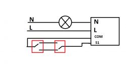
    If you can configure the bell switches as pressing changes the state:
    Zigbee Lighting Control with Tuya Relays: Stair Switch & Wall Remote Setup .
    If you keep the existing connections and you will be able to make the connections (that's by specification):
    Zigbee Lighting Control with Tuya Relays: Stair Switch & Wall Remote Setup .

    To check what the configuration options are and how the relay will behave when controlled from the app and switches for example.

    If COM and L or N are connected it can still simplify the diagram.
    Helpful post? Buy me a coffee.
ADVERTISEMENT