logo elektroda
logo elektroda
X
logo elektroda

Connection of Tuya Smart Home module to an installation with 3 staircase and cross switches

pajutoja2 237 6
ADVERTISEMENT
Treść została przetłumaczona polish » english Zobacz oryginalną wersję tematu
  • #1 21526434
    pajutoja2
    Level 2  
    Hi,
    I'm in the process of planning an electrical installation at home and have encountered a conundrum as to how to connect a smart home device from Tuya to an installation with lighting.
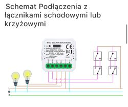
    The diagram would look as follows: 2 light circuits, 3 double switches (2 staircase, one cross) and I don't know how to connect this to the module from Tuya. The cables haven't been laid yet, so maybe someone can help how to do it right. Below are 2 diagrams that I would like to connect together.
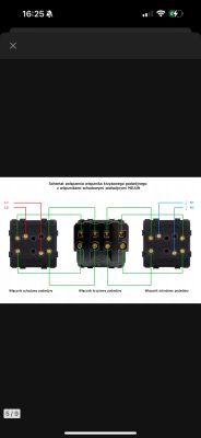
    Wiring diagram for connecting three switches (two double stair switches and one double cross switch) in a lighting circuit. .
    Diagram of Tuya Wi-Fi module connection with two lighting circuits and staircase or crossover switches. .
  • ADVERTISEMENT
  • #2 21527004
    techlock
    Level 28  
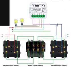
    You connect according to the diagram as for a cross connection.

    Wiring diagram for a Wi-Fi switch module with double staircase and double cross switches and light bulbs. .
  • ADVERTISEMENT
  • #3 21530989
    pajutoja2
    Level 2  
    Is anyone able to diagram this for me yet along with connecting to the network? I'm trying this way but something must be going wrong. The tuya works, but the switches don't.
  • ADVERTISEMENT
  • #4 21531004
    techlock
    Level 28  
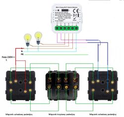
    You have drawn.
    L1 and L2 are the power line (Phase)-the wire colour 230V brown or black
    N-neutral - cable colour blue
    PE-ground - wire colour green/yellow

    You connect the N wire directly to the lighting point (bulb), and to the power supply of the SMART module
    L wire is connected through the switches and the SMART module as shown in the diagram.

    Connect these switches on the table for a test, it appears that you are connecting the switches incorrectly.

    Diagram of Wi-Fi switch module wiring with double stair and crossover switches to control two light bulbs. .
  • #5 21531118
    pajutoja2
    Level 2  
    After further tests it appears that the problem is with the cross-over, most likely I have a faulty switch, on the two stair switches alone everything works.
  • ADVERTISEMENT
  • #6 21531455
    adamjur1
    Level 41  
    Don't blame the equipment just check the connection five times. An arrangement of two staircases and one cross-over in the middle and yet all of this times two and in shared boxes is heavily complicated, it's easy to get lost; many times I've rescued less patient contractors once they've given up.... And sometimes they would abandon the customer saying that something was in the cables and "it's not possible"
    Greetings. J.
  • #7 21531892
    pajutoja2
    Level 2  
    A solution was found! Final cross switch working, as a colleague wrote, but I didn't mess up the wiring, and the diagram from the manufacturer for connecting the switches was wrong. To make it work, it's a diagram as above, but with the difference of plugging in the cross switch. Looking at the diagram above, the wires going from the left hand staircase should be plugged into the top wires on the cross-over (not 2 top and 2 bottom from the left as in the diagram), and down plug the wires going to the right hand staircase, plugging in the wires, keeping the analogy of plugging in from the top wire on the left hand staircase.
    And then everything works: both staircase, cross and Tuya :) .

Topic summary

The discussion addresses the integration of a Tuya smart home module into a lighting installation featuring two light circuits controlled by three double switches arranged as two staircase switches and one cross switch. The installation wiring should follow a cross-connection scheme, with the neutral (N) wire connected directly to the light fixtures and the smart module's power supply, while the phase (L) wire is routed through the switches and the Tuya module. Initial issues with switch operation were traced to incorrect wiring of the cross switch rather than faulty equipment. The correct connection involves swapping the wiring on the cross switch so that wires from the left staircase switch connect to the top terminals of the cross switch, and wires to the right staircase switch connect accordingly, differing from the manufacturer's original diagram. This corrected wiring ensures proper function of both staircase and cross switches alongside the Tuya smart module.
Summary generated by the language model.
ADVERTISEMENT