Elektroda.com
Elektroda.com
X

Holter ECG (AD8232, Bascom, KokkeKat FAT)

saycomp 14265 29
This content has been translated flag-pl » flag-en View the original version here.
  • Hi!

    I wanted to share with you the description of the construction that my life forced me to make.
    I had some periodic heart problems and every time I got Holter it all calmed down ;)
    If any of you have ever tried to sign up for Holter, you know that it is not easy. He waits and waits.
    I decided to take matters into my own hands and build a simple, single-channel device.
    While searching the internet, I came across a specialized differential amplifier (AD8232) with a filter, which is used in heart rate recorders. So I decided not to balance the open door by building a differential amplifier from scratch and ordered a few pieces of this circuit.
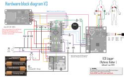
    The layout is located on a double-sided PCB with dimensions of 42 x 32 mm. The use of the AD8232 chip requires a fairly precise PCB - the pins of the system are in a 0.5 mm raster. I make the tiles using photosensitive foil to expose screen printing screens. As a cliché, I use tracing paper printed on a laser printer and optically compacted in vapors of nitro thinner. The guides are Bungard 0.6 mm (O.D.).
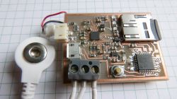
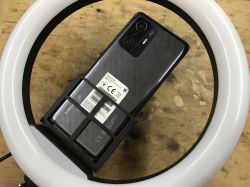
    Holter ECG (AD8232, Bascom, KokkeKat FAT) Holter ECG (AD8232, Bascom, KokkeKat FAT) Holter ECG (AD8232, Bascom, KokkeKat FAT)

    The system is powered by a small Li-Poly 250 mAh battery. Its capacity is enough for about 5-7 days of continuous operation.
    The battery is charged via the microUSB socket and the MCP7381 system, and the power supply to the system is provided by the MCP1703 stabilizer (3.3 V).
    The amplifier operates in the configuration shown in the catalog note in figure 68 (PORTABLE CARDIAC MONITOR WITH ELIMINATION OF MOTION ARTIFACTS).
    The signal from the amplifier is fed directly to the ADC input of the Atmega 168 controller.
    One TACT button is used to operate the recorder. Long (> 3 s) press turns on / off, short press is "event button" - it gives a characteristic, well recognizable pin in the record.
    The blue diode shows that the button is pressed, the green diode shows active recording, the red diode shows a card error or the disconnection of one of the electrodes.
    The recorder saves on the card hourly files in binary format, 16 bit unsigned and with the sampling frequency of 250 Hz. Numbering is automatic from "000.PCM"
    The easiest way to preview a recording is to open it in an audio processing program (Audacity - free, Audition - paid), which allows you to preview the graph in a large window (Audacity: view -> vertically fit).

    The construction of the Holter was also an opportunity to "face" an alternative to AVR Dos - the KokkeKat FAT library. KokkeKAT allows you to use a processor with less RAM than AVR Dos. And here, unfortunately, I must say that it is better to invest in a larger processor and use AVR Dos than to fight KokkeKAT. The latter is very capricious, poorly documented, and there are very few described structures operating with it. It is also not updated and corrected. Following the attached PDF file will result in either compilation errors or failure to read / write to the card. Until the end, I was unable to read the entire 8 + 3 file name. Only works for names no longer than 4 characters plus the extension. And not always. Reading the file name often fails and the processor (after a reset) writes the numbering over again, luckily without overwriting the existing files. Fortunately, this is not a big problem. You just have to remember to delete all files from the card in case of reprogramming the processor or disconnecting the power supply. If any of you want to bite into the program, I will be happy to find out where I made a mistake.

    The plate design (Corel 9, PDF) and the program files are attached.

    Best wishes

    Cool? Ranking DIY
    About Author
    saycomp
    Level 12  
    Offline 
    saycomp wrote 67 posts with rating 50. Live in city Wrocław. Been with us since 2005 year.
  • #2
    hobbyelektronik
    Level 27  
    Hello

    I can see one electrode in the photo, maybe I am wrong, while ECG uses 12-15 electrodes as standard, while checking the heart rate requires 3 to 5 leads. Each of them has a specific place on the body.

    The electrodes are divided into:

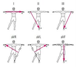
    bipolar I, II, III,
    unipolar aVL, aVR, aVF,
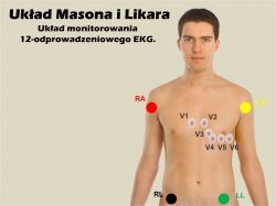
    precordial V1, V2, V3, V4, V5, V6.
    The red clip is placed on the right wrist, the yellow clip on the left wrist. The black clip is on the right ankle, and the green clip on the left.

    Best regards and congratulations on the idea.
  • #3
    saycomp
    Level 12  
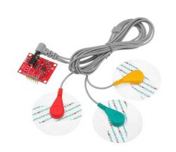
    I only put one electrode in the photo to show that I used system solutions. There are actually 3 electrodes - one "zero" and two differential for one channel (you can see 3 wires coming from the recorder).
    This is the easiest way to record the electrical activity of the heart. It allows for a preliminary assessment of problems. A similar single-channel system is used, for example, in AED defibrillators. Multi-electrode (multi-channel) systems are used for detailed problem analysis. But to be able to correctly read the record from such a multi-channel device, you need a lot of knowledge (many years of study).
  • #4
    LechU
    Level 14  
    Yes, to be precise: the standard ECG test is performed with 10 electrodes - 4 limb electrodes ("R", "L", "F", "N") and 6 precordial electrodes ("V1" ÷ "V6").

    Leads "I", "II" and "III" are obtained from the same electrodes as "aVR", "aVL", "aVF" - limb electrodes.

    Holter ECG (AD8232, Bascom, KokkeKat FAT)


    The remaining electrodes - "V1" ÷ "V6" "are used - as you can easily guess :D - for measuring leads "V1" ÷ "V6".

    Holter ECG (AD8232, Bascom, KokkeKat FAT)


    It is therefore necessary to distinguish the number of electrodes (there are 10) from the number of leads (and there are 12 of them).

    Of course, there are simplified systems - commonly used in cardiac monitors - 3 electrodes and 5 electrodes, as well as more complicated ones - differing mainly in the number of precordial electrodes - I was surprised when I got an EKG repair, which instead of the standard 6 had 8 precordial electrodes.
  • #5
    Janusz_kk
    Level 36  
    LechU wrote:
    Yes, to be precise: standard ECG test

    But the Holter is not a standard EKG, it only has three electrodes and that's it.
    Apparently enough to see deeper heart disorders is enough, I also had it done and showed something.
  • #6
    LechU
    Level 14  
    YES, YES and YES again!

    My correction (?) Concerned post # 2 - which had some confusion with the nomenclature (leads vs. electrodes).

    In the simplest case, 3 electrodes are enough - 2 as a differential input and 1 neutral - which was what my colleague saycomp used in his (incidentally very interesting and interesting) solution - CONGRATULATIONS!
  • #7
    kroolik1989
    Level 10  
    Can you show the device operation graph?
  • #8
    Piotrek1970
    Level 18  
    From what I can see this is the second and third photo in the first message.
  • #9
    krzbor
    Level 25  
    I didn't know there were such arrangements. As I read the article, I thought about an expensive and rare integrated circuit. I entered it in google and here's a surprise:
    Holter ECG (AD8232, Bascom, KokkeKat FAT)
    banggood offer for PLN 44. I also found heart monitoring systems with this module on the contact plate :)
    Another problem remains - how to read the data. If there are specialists on this forum who know something about it, I have a request that they share this knowledge.
    Here is the original sparkfun and some interesting information Link
  • #10
    bar-t
    Level 10  
    Where did your colleague get these leads with electrode connectors? Does this connector have a name? In my searches, I was able to find some ready-made sets of cables for several dozen euros.
  • #12
    ostry_18
    Level 24  
    krzbor wrote:
    Another problem remains - how to read the data

    A single-channel ECG will give the doctor the basic possibilities of recognizing the nature of an arrhythmia, sometimes it will answer the question of what type it is. Moreover, it is a completely objective way to distinguish subjective "palpitations" from real arrhythmias.
  • #13
    krzbor
    Level 25  
    Question to the author of the thread - can you interpret the second graph? The first one is nice, almost textbook. The second is different - significant difference in amplitude - measurement error or actual change in heart rate? There are visible differences in the period - this is probably not a mistake. A lot of additional signals - disturbances or reality?
  • #14
    ostry_18
    Level 24  
    krzbor wrote:
    The second is different - significant difference in amplitude - measurement error or actual change in heart rate? There are visible differences in the period - this is probably not a mistake. A lot of additional signals - disturbances or reality?

    Numerous additional supraventricular stimuli, artifacts.
  • #15
    excray
    Level 40  
    krzbor wrote:
    banggood offer for PLN 44.

    On Aliexpress, there is a plate with wires below PLN 20.
  • #16
    saycomp
    Level 12  
    krzbor wrote:
    Question to the author of the thread - can you interpret the second graph? The first one is nice, almost textbook. The second is different - significant difference in amplitude - measurement error or actual change in heart rate? There are visible differences in the period - this is probably not a mistake. A lot of additional signals - disturbances or reality?


    This is atrial fibrillation.

    bar-t wrote:
    Where did your colleague get these leads with electrode connectors? Does this connector have a name? In my searches, I was able to find some ready-made sets of cables for several dozen euros.

    Cables - search on Allegro: tens
    electrodes in the same place: ecg electrodes

    krzbor wrote:
    Another problem remains - how to read the data. If there are professionals on this forum who know something about it, I have a request that they share this knowledge.


    The matter is very simple. The AD8232 outputs an amplified (and filtered) signal of the electrical activity of the heart. You can connect this output to an oscilloscope and watch it live, you can also save it on some medium and later analyze the data offline. Data analysis is not easy. The most basic heart problems can be picked up after a few days of study. Years of training are required for in-depth analysis. The fact that this is a very complex knowledge is proved by the fact that there are really few good cardiologists.
  • #17
    boreas9
    Level 2  
    This is called atrial flutter, however irregular.
  • #18
    Hanslik
    Level 10  
    Hi
    By using this topic (hopefully neither the author, nor the administration, nor any of the users will be angry) as it is very topical, especially in the times we have today. First of all, I would like to congratulate you on a great idea and execution.
    I also plan to do such a Holter, and therefore a few questions.

    Does your system record continuously after a long button press?
    Does the system record in real time? - for precise reading at which point / time of the day the anomaly occurred, e.g. after waking up from a nap, etc.

    However, I am not as talented as you, therefore I would like to ask you for help in selecting components. I decided to shop for botland.

    DFRobot Gravity - heart rate monitor - analog heart rate sensor of the human heart

    DFRduino Uno v3 - compatible with Arduino

    DFRobot Gravity - IO Expansion Shield for Arduino V7.1

    Set of connecting cables 20cm 3 x 40 pcs. mm, f-f, m-f (120 pcs.)

    Do you have any suggestions on what else should I buy to construct such a project?
    - create an interface
    - enable data dump to the computer
    - enable mobile operation (battery)
    - add a button for sudden event recording
    - other necessary or useful components

    I watched various guides on Youtube, unfortunately they all show the operation of the EKG - the current signal recording on the computer / oscilloscope, and I just care about the Holter.
    The money issue plays a minor role, so if you have any ideas that will improve the project I will be very grateful for suggestions and help :)

    best regards
  • #19
    saycomp
    Level 12  
    Welcome.
    Long press turns the system on / off. Registration is continuous when the system is turned on. A short press gives a characteristic pin on the graph. In this way, you can mark the moment of problems, awakening, etc.
    The system does not have a clock, the time can only be estimated by the number of files and the file location.
    I don't know which programming language you are tuned to. Do you want to use my source or do you want to write from scratch in Arduino?
    As for your list, the first position is OK. When it comes to the Arduino hardware platform, I can't help much - I don't use it and I don't know anything about it (I think it limits the freedom of design too much).
    Quickly judging - I think it is average for this:
    1. It is power-hungry - the 7805 stabilizer itself consumes several times more electricity than the Atmega.
    2. The controller (Atmega 328) that works in it can be powered directly from one Li-Ion battery (3.2 - 4.2 V). However, Arduino has its own stabilizer that needs to be powered with a higher voltage, minimum 5V.
    In this situation, I would recommend to use only the controller on the board and power it with one Li-Ion cell:
    https://botland.com.pl/pl/plytki-zgodne-z-ard...-3162.html?search_query=atmega+328&results=11
    You also need to add a plate with a memory card slot.
    If you want to use my program, the Atmega 328 is "tight" using SRAM.
    If you want to write from scratch, choose a controller with more SRAM and depending on the development environment use some well-known and proven library to handle the memory card.
    I do not know the Arduino language and I do not know what write speed on the card can be "pulled", but KokkeKAT supported by NoSave Tool is barely made at 250 Hz sampling and writing 2 bytes per sample (processor powered just over 3 V has a maximum clock frequency of 8 MHz ). Let the experts say whether it is feasible with Arduino.
  • #20
    Hanslik
    Level 10  
    Hi
    Thank you for your answer.
    For me, you are a professional, unfortunately I can only call myself a beginner, especially in the field of electronics / automation.
    I do not want to take any steps rashly, so I will wait for other comments.
    Do you think that Arduino's power consumption will make it difficult / impossible to record the characteristics around the clock?
    For a long time it seemed to me that this is one of the more developed environments, most of the na yt tutorials use this equipment, hence the quick concept for using Arduino.

    I don't know any language, but I know that there are ready-made applications for Arduino available - maybe some text could be slightly edited to make the job easier?
  • #21
    krzbor
    Level 25  
    When choosing a platform to build a Holter, I would consider ESP8266, e.g. Link or Link In ESP, you can turn off Wi-Fi and transfer data to SD (there is SPI).
  • #22
    Hanslik
    Level 10  
    Thank you for another tip, now it will be easier for me ;)
  • #23
    Piotrek1970
    Level 18  
    saycomp wrote:
    As for the Arduino hardware platform, I can't help that much - I don't use it and I don't know anything about it (I think that it limits the freedom of construction too much)

    Colleagues, first of all Arduino is a "development" kit and as such meets all the requirements to help find possible problems at the stage of project development. Having access to various types of kits, you can go all the way from the idea to the final project. partially working application, you can go a step further and create your own PCB with the power supply we need, select the voltage / frequency of the microcontroller to obtain the most satisfactory working time, e.g. on a single Li-Po cell.
    The fact that in this application the key assumption is to work long on the available power source, but to blame the development kit for being universal and not able to meet the requirements of a special project is an abuse.
    To colleague Hanslik : before you start building your own device or try to copy the idea of saycomp [col. provided the program files for the project], consider asking the originator to make one [or more] such tiles for you and pay for his work honestly, but if you plan to independently learn the design and programming of microcontroller systems, this is a good time to taking up the challenge ;-)
  • #24
    saycomp
    Level 12  
    Piotrek1970 - I completely agree with you about the development value of Arduino. I meant that relatively simple constructions, with a little experience, can be made "from the shot", with dedicated solutions. For beginners, I recommend starting with ready hardware.

    Hanslik - if I'm allowed to suggest, get into programming "soft", don't jump into the deep end. In theory, the program works like this: the timer triggers the interrupt 250 times per second and in this interrupt an analog signal sample is taken by the converter. After light processing and adapting to 16-bit form, it is saved in the buffer and in the main program loop the buffer is dumped on the memory card. Seems simple, but there are a lot of smaller and bigger hooks along the way (card initialization, file name organization, card error checking, button handling etc - it makes quite a mess). I speak reasonably good the programming language I write in, but it took me a good 4 afternoons to write a working program (90% of the time to understand why KokkeKAT doesn't work) ;) ) + several evenings for fixes and improvements.
    Begin, as everyone recommends, by blinking the LED attached to the microcontroller ports and gradually increase the difficulty. If you start at a high level right away, it is very easy to get discouraged by failures and to overlook important issues regarding the language itself, program structure, its optimization, etc.
    When it comes to choosing a language and environment, you have 3 options with the most popular 8-bit controllers: Bascom, C / C ++ and Arduino.
    The internet is full of discussions about the superiority of one over the other. I chose Bascom, mainly because of the speed of development and lightning fast compilation. It requires a paid program and some people think it gives the worst result code (slow and big - not true in my opinion). Its undeniable disadvantage is the least number of libraries to support various peripherals and the "closed" program code, depending on the manufacturer. The biggest advantage, especially for a novice, learning speed and simplicity.
    C / C ++ - quite difficult to learn, especially at the beginning it seems confusing and not obvious. "All in one" you have in the program from the manufacturer - Atmel Studio. Unfortunately, the program is large (a few GB) and sluggish. The beginnings are frustrating.
    Arduino seems to be the most developmental environment at the moment. There are tons of manuals, hardware libraries, and examples. You program in practically C / C ++, but the beginnings are much easier and more enjoyable thanks to the transparency and undeniable simplicity of the program. Some inconvenience when building your own hardware is the need to load a special "arduin" bootloader to the CPU and the slow compilation.
    This is my private opinion, which is not necessarily completely objective ;)
  • #25
    Hanslik
    Level 10  
    Hi everyone

    @ Piotrek1970
    I would like to pay for complete help in designing the schematic and code, although I think it will be hard to find volunteers and I will have to deal with it myself, so learning will not pass me by. I picked up a few more components in the store and I think I'll order today.
    I decided to design the system on Arduino and use at least some of the available libraries.

    @saycomp

    As I wrote above, despite the divided opinions, I will use Arduino. As for the problematic uploading of updates, there are supposedly overlays that improve this process.

    When it comes to the functionality of the device, I have two options:

    buy:

    ESP8266 WiFi Shield - Shield for Arduino - SparkFun WRL-13287

    WiFi module ESP8266 Wemos NodeMCU V3 32MB - 11 GPIO, ADC, PWM

    and put on data transfer to a cloud server - on the phone (I think this is a complicated idea, because it requires the addition of an Android application)

    or purchase:

    LiPower Shield - Arduino power supply from a Li-Po battery module - SparkFun DEV-13158

    and set yourself up for the operation of the battery-powered system, and the whole thing will be recorded in flash memory available for reading on a computer.
    When using the second solution, the question arises:
    Wanting to use the Arduino mentioned in the post above, I noticed that the manufacturer gives a supply voltage of 7-12 V
    And the above system provides a constant power supply of 5 V - does it mean that the system will not work? The original Arduino Uno V3 also has a fixed voltage of 7-12 V. If anyone knows this topic, please correct it.

    How do you rate the first and second idea?

    Please note that I do not take into account the convenience of use - it is only supposed to fulfill its function.
  • #26
    krzbor
    Level 25  
    This NodeMCU sold by Botland made me laugh - 32 MB flash and 800/1600 MHz frequency - it's a real performance demon :) I am not surprised by the sellers' mistakes "soap and jam" - they do not understand what they say, but I thought about Botland as a specialist company. Valid data is 4 MB of flash (32 Mb) and frequency of 80/160 MHz.
    Coming back to the question - if you want to send data to the server, it is rather to some Apache / Nginx machine with PHP. Or just like the author of the thread - to the SD card: Link . However, you need to evaluate your options. Thanks to the modules, it is relatively easy to deal with the layout from the "electric" side, but the programming side requires some programming knowledge and skills.
  • #27
    Piotrek1970
    Level 18  
    Hanslik wrote:
    Wanting to use the Arduino mentioned in the post above, I noticed that the manufacturer gives a supply voltage of 7-12 V
    The supply voltage of the Arduino module results from the possibility of the stabilizer used in the project. In this case, for the system to work properly, there must be a 'reserve' of the input voltage in relation to the output 5V, and in this system it is safe to have a reserve of 2V and more. The second voltage parameter is the maximum value and thus the power that can be 'lost' in the controller. In this case, 12 V is given, if you subtract 5 V from it, the difference is 7 V * I (max), which will be transferred to the system in the form of heat :-( and this is an unnecessary waste of energy.
    The Arduino board can also be powered directly from USB, where it is 5 V, or via PIN_5 V.
    If you want to reduce the 'consumption' of electricity by the microcontroller, you can switch to the internal clock circuit and lower the operating frequency of the system -IMPORTANT NOTE: incorrect setting of the so-called FUSE bits can block the microcontroller circuit. Recovery is possible, but requires a little 'exercise'.
  • #28
    Piotrek_I
    Level 11  
    @saycomp Where do you open these files and draw the graph later?
  • #29
    saycomp
    Level 12  
    I open in Audacity, you can also in Audition.
    You just need to define the file parameters. Later screenshot or export, e.g. to a text file and open in Excel.