Admission
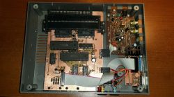
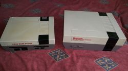
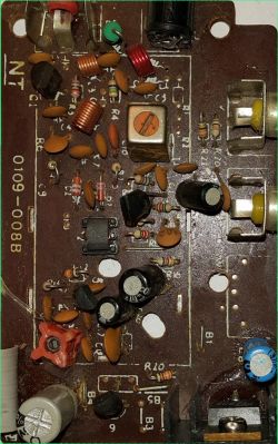
Recently, an interesting console fell into my hands - Daryar DY-636N. I gave it the nickname "Mini NES" because at first glance it looks very similar to the original NES. Only a closer comparison reveals that it is slightly smaller and lower. Its extraordinary advantage is that it has two cartridge slots - a standard Pegasus 60 pin (on the top) and a NES 72 pin (on the front). Inside the console, there is also a third 60-pin socket to accommodate a PCB with a built-in assembly, but it was empty.
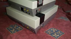
The next difference is the construction of the 72 pin cartridge socket - in NES it is the so-called shelf (ZIF - Zero Insert Force), which requires pressing down after inserting the cartridge. Here we have a standard edge socket, but angular
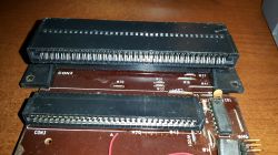
In the past, I even came across something very similar, only with a single 72 pin socket, but inside there were integrated circuits and a game component integrated with the motherboard: https://forums.nesdev.com/viewtopic.php?t=19027
Unfortunately, the console that is the hero of this thread turned out to be damaged - the voltage measurement on the damaged (most likely after connecting the power supply with wrong polarity) stabilizer 7805 on the output side showed approx. on the gluta-main processor only additionally confirmed this belief)
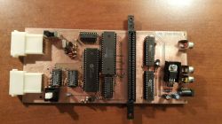
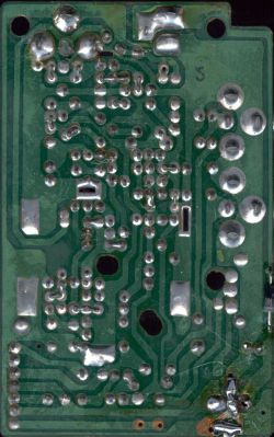
However, it was very important for me to save her. Due to the unusual housing, the only option was to make the motherboard from scratch on the chips. By the way, I recreated the motherboard diagram:
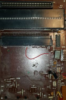
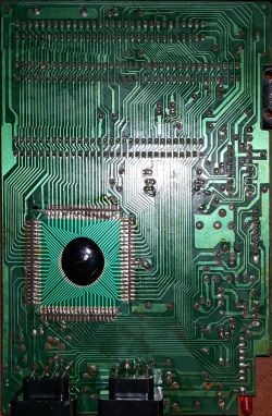
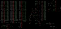
and plates with sockets:
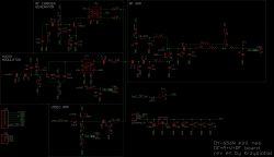
Usually, in this type of schematic I omitted the modulator completely, but for some time I started to be interested in how they are built and I encountered several different, more and less complex designs.
Motherboard design
Making motherboards from scratch to consoles is - you might say - my bread and butter.
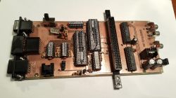
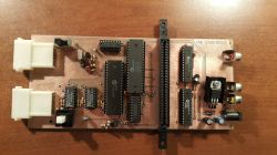
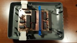
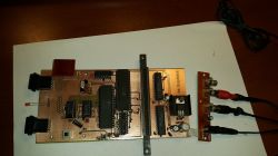
I usually use my proven scheme and mosaic of tracks and only slightly adjust it to some housing (e.g. by moving mounting holes, pad sockets, power sockets, power / reset buttons or audio and video sockets). Here, of course, we had to add a second cartridge slot (which was a minor concern, because the pinout of this slot is basically a mirror image of the 60-pin pinout). A minor macro is that the pins' raster is 2.5 mm, not 2.54 mm as for the 60 pin socket, which involved the necessity of constantly switching between millimeters and mils in the Eagl to run the track once centrally between the pins of the 60 pin connector, and then centrally between the pins of the 72 pin connector.
The bigger worry was that behind the cartridge slots, where there are RAM memories in the above projects, there was no more space in this console. I had the idea to divide the PCB into two parts and place one under the other, but I decided not to "choke" and put everything on one. This required replacing the narrow RAM with wider ones, so I could run a small highway of paths underneath them.
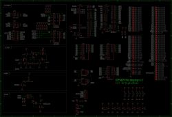
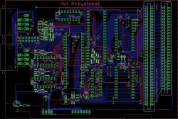
However, I was not entirely satisfied with this solution - just compare the number of vias in this and previous boards around RAM. This clearly confirms that the optimal place for these memories is behind the sockets.
The last fitting (I had the greatest concern that the places for the ginazda pads and cartridge slots would match the appropriate holes in the housing):
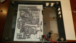
The tiles came out great:
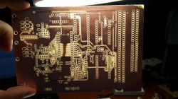
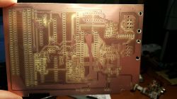
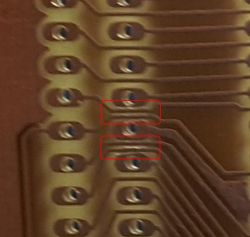
The only problematic place (which even Eagle warned about) was below - I had to cut the slight indigestion of the pad tracks with a knife. Well, here are two tracks of 0.01 mils between 1.5 mm pads (bigger than standard Eagle pads from scalers), which is 0.006mils of clearance.
Expansion slot
The keen reader will notice that there is a mysterious 2x8 goldpin socket on the board. In a word of explanation - consoles have two several-bit input ports (available at addresses $ 4016 and $ 4017) with their clock signals ($ 4016.CLK / $ 4017.CLK) and a three-bit output port (OUT0, OUT1, OUT2). Different accessories use different lines as shown in the table below
                           | $4016 $4016 $4016 $4016 | $4017 $4017 $4017 $4017 4017 $4017 | OUT2 OUT1 OUT0 | Uwagi
                           |    .2    .1    .0  .CLK |    .4    .3    .2    .1   .0  .CLK |                |
---------------------------+-------------------------|------------------------------------+----------------|---
Joystick gracza 1          |                 x     x |                                    |              x |
Joystick gracza 2          |                         |                            x     x |              x |
Standardowy pistolet       |                         |     x     x                        |                |
Joystick gracza 3          |           x           x |                                    |              x |
Joystick gracza 4          |                         |                       x          x |              x |
Klawiatura Family BASIC    |                         |     x     x     x     x            |    x    x    x |
In all NES clones of this type, only the lines: $ 4016.0, $ 4016.CLK, $ 4017.4, $ 4017.3, $ 4017.0, $ 4017.CLK, OUT0, required by pads 1, 2 and the pistol are shown. However, in the original famicom (and most of the better pegasuses) all lines are output (available on the 15-pin expansion port). I also decided to lead them out on the connector in order to be able to connect them with tape to an additional connector later.
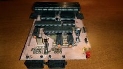
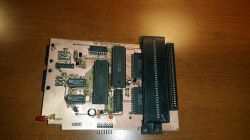
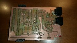
After soldering, everything worked from the first time
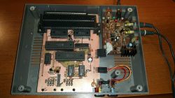
Doting the "i" was just:
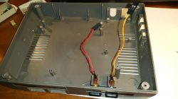
* making plugs for the POWER and RESET buttons (previously the wires were permanently soldered to the board)
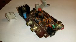
* replacement of the original heat sink from the stabilizer to a larger one (the console on scalakch requires much more electricity = much more heat):
Mistakes
I didn't manage to avoid a few faux-paux though:
1. Sockets of the rainfall No. 1 and the rainfall number 2 were mistakenly changed with each other
2. I led the paths to the pads from both sockets so that they had to be soldered from the "elements" side (they were also like that on the original, damaged PCB). Here I came up with the idea of drilling small holes next to the holes for the legs and passing them wires that would connect the layers to be able to solder the legs of the sockets from the other side:
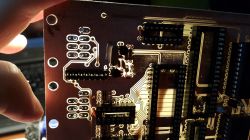
3. Once I got a cable with a socket for connecting the 15-pin expansion port, I noticed that the plug was too high, so the casing would not close, because just above the socket in the upper part of the casing there is a flat "cage" in which the cartridge is placed:
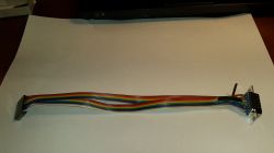
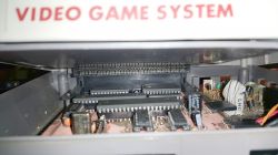
I thought a bit about how to solve it, until I came up with the idea of replacing the previously made plug with an IDC plug, which is 1-2 millimeters lower:
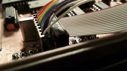
Additional ports
Going to the store on a bicycle 30 km one way, I had some time to think. I thought about why I should only output a 15-pin expansion port, if you would need more adapters if you wanted to connect standard pegasus pads. And so I figured out that I would output all 4 possible combinations at once: player 1 - port 9 and 15 pin and player 2 - port 9 and 15 pin. The 15 pin port from player 2 also functions as an expansion port.
I was wondering how and where to place these ports (all next to each other, one below the other). After all, it turned out to be a natural place where the last free space inside the case was. So I made a suitable board to which I could connect the IDC tape with a previously designated socket:
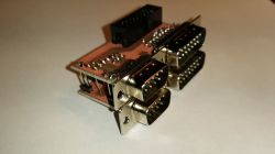
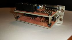

It took me about 2 hours to cut the right place in the casing (I tried a cutter, a manual file, and finally a mini-disc saved me from a dremel). And since I was already drilling well after midnight, from this place I would like to heartily greet my neighbors:
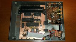
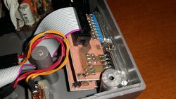
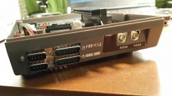
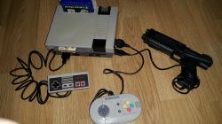
Finally, however, a console was created that allows you to connect any type of pad (7, 9, 15 pin) and any type of cartridge (60 pin and 72 pin):
Cool? Ranking DIY


