Hello,
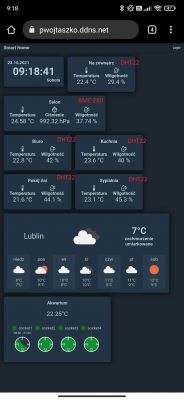
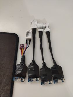
I am building myself a simple home management and information display panel (smart home). I have invested in 5 DHT22 sensors and 1 BME280. I have built 5 microcontrollers from this.
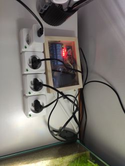
1. socket control, waterproof temperature probe and DHT22
2,3,4. DHT22
5. DHT22 and BME280
I connected everything according to schematics found on the internet with 10k between VCC and data.
I soldered everything together to start using it, I left it connected overnight so that each sensor lay in the same place and unfortunately each sensor shows different values. (Analogue thermometer showed 23.6 degrees)
Initially I wrapped the circuits with insulating tape but ultimately they were to have their own boxes.
I'm a bit disappointed with how it looks. I hope someone here can help me with this problem.
The code for circuits 2,3 and 4. The rest of the circuits take DHT similarly:
Link to github .
.
.
.


