logo elektroda
logo elektroda
X

BG Electrical 822/HC-01 RDA5981A BL3335-P Module Double UK Smart Socket

gandi69 84 25
ADVERTISEMENT
  • #1 21712646
    gandi69
    Level 2  
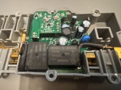
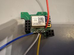
    Hi was any further progress made on this? I have a double socket (UK 3 pin) with one of these fitted (BL3335-P) which comes fitted to a handy unpluggable module so it would be quite easily to flash

    Moderated By p.kaczmarek2:


    Posts split from https://www.elektroda.com/rtvforum/topic4105474.html

  • ADVERTISEMENT
  • #2 21712657
    divadiow
    Level 36  
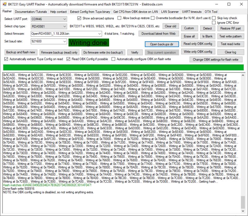
    well, you'll see from the thread and various screenshots that OpenRDA5981 exists and does run on RDA5981. I've not flashed my BL3335-P UK plug to the latest release and attempted to make a working device so I cannot comment on its stability or full functionality at this point. Know that with no OTA ability, any improvements and fixes will require wired flashing every time.
  • ADVERTISEMENT
  • #3 21712664
    gandi69
    Level 2  
    OTA isn’t a major concern for me for now. Do you think it will be available in the Windows based flashing tool? Or is there a compiled bin file available for download at all? Please forgive my ignorance on this topic I’ve only started flashing openbeken in the past week or so
  • #4 21712734
    divadiow
    Level 36  
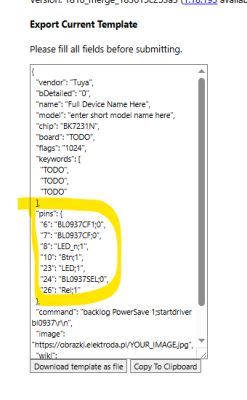
    there isn't an Easy Flasher function for RDA5981 but there is RDA's own Windows tool for dumping and flashing firmware.

    https://github.com/openshwprojects/FlashTools/tree/main/RDAMicro

    A couple of those there do the same thing but are different versions. There isn't a single how-to guide yet for RDA but the process is demonstrated, with tool screenshots, in earlier posts in this thread.

    gandi69 wrote:
    Or is there a compiled bin file available for download at all

    OpenRDA5981 is available from the release pages https://github.com/openshwprojects/OpenBK7231T_App/releases

    Added after 10 [minutes]:

    divadiow wrote:
    There isn't a single how-to guide yet for RDA but the process is demonstrated, with tool screenshots, in earlier posts in this thread.


    I could do one tonight I guess with real BroadLink plug
  • #5 21713350
    gandi69
    Level 2  
    Thank you, I will try this when I can. Once I remove it I hope to be able to find the necessary pin to flash I’m assuming there is a cen pin which should go high or to ground?
  • #6 21716496
    gandi69
    Level 2  
    I managed to get this flashed with OpenRDA - no extra pins needed other than voltage, gnd and tx/rx. Hopefully I can make this work with the UK double outlet/socket that are stocked at most large retailers in the UK as there are not many choices other available than these ones currently, at least for a reasonable price. thank you all for your hard work
  • #7 21716513
    divadiow
    Level 36  
    good show. let us know how you get on

    Added after 26 [minutes]:

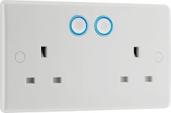
    Also, is your unit a BG Electrical double like this?
    BG Electrical 822/HC-01 RDA5981A BL3335-P Module Double UK Smart Socket

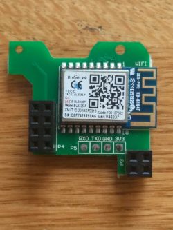
    With this module?
    BG Electrical 822/HC-01 RDA5981A BL3335-P Module Double UK Smart Socket
  • ADVERTISEMENT
  • #8 21716534
    gandi69
    Level 2  
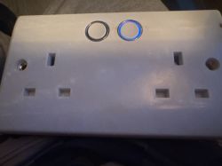
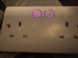
    Yes that is the device I have these are very common and cheap here in the UK. LED configs are a problem for me though as I cannot work out how to fire the blue LED ring per switch as this unit requires the relay to be on so it can fire the GPIO pin for the corresponding ring to light. Currently I have one ring firing blue for relay 2 and one firing both in red for relay. If I try to mimic the config of relay 2 on relay 1 it doesn’t light. Not a huge problem but could be an issue if someone uses the switch manually which is unlikely for my use case

    Relay 2 on


    BG Electrical 822/HC-01 RDA5981A BL3335-P Module Double UK Smart Socket

    Relay 1 on

    BG Electrical 822/HC-01 RDA5981A BL3335-P Module Double UK Smart Socket

    Added after 1 [minutes]:

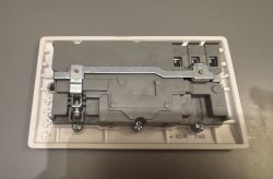
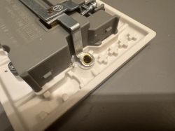
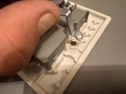
    Another note you have to kind of butcher the earth strap across the back of the unit to get to the innards of this device as it uses a brass rivet arrangement for earths, I will attempt to fix this later so it is safe and tidy
  • #9 21716572
    divadiow
    Level 36  
    hmm ok. what does your current template look like in terms of pin assignments and channels?

    Added after 54 [seconds]:

    eg
    BG Electrical 822/HC-01 RDA5981A BL3335-P Module Double UK Smart Socket
  • #10 21716841
    gandi69
    Level 2  
    This is mine

    Code: JSON
    Log in, to see the code
  • #11 21719456
    gandi69
    Level 2  
    That setup works perfectly for the right hand side button (but it can be either side it’s just my config is set that way). I can make the button press for the left hand side turn on the relay but not the light. However if I use the GPIO finder in the web app I can manually do it by firing the 3 pins themselves by the web UI buttons. Hope that makes sense.

    Like I say not the biggest deal ever but it would be nice if it worked as the OEM software does
  • #12 21719476
    divadiow
    Level 36  
    it does make sense and I think your config looks right for what you want, though I seem to be struggling with some basic things this evening, hence the deleted post I made earlier.
    presumably LED_n makes no difference? that would just put the LED on but with relay in wrong state, ie the opposite.
  • ADVERTISEMENT
  • #13 21719545
    gandi69
    Level 2  
    I think I have tried that but no luck- I spent about 3 hours trying to get it to behave with no luck. I’ve flashed another socket now which is connected to a plug and flex cord so I’ll be able to test more easily.
  • #14 21719559
    divadiow
    Level 36  
    if the relays are taken out of the equation is the situation the same? ie you can't control LEDs alone with each button still?

    like

    "3": "Btn_n;1",
    "4": "Btn_n;2",
    "8": "LED;2",
    "25": "LED;1",
  • #15 21719588
    gandi69
    Level 2  
    I will need to test that for 100% confirmation but from what I remember the LEDs require their respective relay to be on to function so you cannot test that way unfortunately
  • #16 21719655
    bertjones
    Level 2  
    >>21719588

    I've had some BG sockets connected to Home Assistant for a couple of years and have always wanted to replace the firmware with something that doesn't continually try to connect to the internet. I've got the sockets blocked by a router firewall rule. They still work but blocking them causes them to drop and reconnect to the wifi regularly.

    I've just found this forum and the very helpful information on it. I've flashed lots of ESP devices but have never flashed Broadcom or Tuya type devices so I'm very new to this. After reading this thread and a bit of experimenting I've managed to do a rom dump of the BL3335-P with its factory settings and a rom dump with my wifi settings in it.
    Hopefully the information below will be of help. Some of it may be obvious to you but as a beginner it wasn't to me. :-

    With the module pcb plugged into the BG socket pcb I powered it from an external 3.3v supply.
    Red leds flashed at boot up. I assume until wifi connected.
    Blue leds go on and off with the power buttons.
    NOTE
    The relays will not turn on as they use a higher voltage power supply that isn't available unless the mains is connected. WHICH IT MUST NOT BE WHILE CONNECTED TO THE USB TO SERIAL ADAPTOR.

    Ran RDA Dump Tool v01.00.03 in Windows 10
    With the default settings :-
    Baudrate 921600
    Dump Address 0x 18000000
    Length of Word 0x3fc00
    Set to 1MByte

    ----------------
    EDIT
    After reading https://www.elektroda.com/rtvforum/topic4148573.html I've realised that the 1M Dump setting doesn't give the full 1M rom dump!
    To get the full dump set Length of Word to 0x7fc00 and Flash Size to 2M, so dump is just short of 2mb. The file can be trimmed down in HxD later.
    Alternatively, select 2mb flash size and word length of 0x3ffff.
    ----------------

    With a USB to Serial adaptor connected to RX and TX and earth. So the 3.3v supply earth and flasher board earth are connected together.

    With the Dump Tool running and connected to the USB to Serial adaptor port, hit Start. Then turn on the 3.3v power to the BG socket. It will connect and create a dump file. You may need to power the BG board on and off a few times before the Dump Tool will connect to it.

    Tried with 1M, 2M and 4M settings and all dump files were 1M in size and the Dumped 100% value was 0x180fc000 in all cases.
    Checking the MD5 of the files and they were all identical.

    When the Dump Tool has connected to the module the red leds do not come on at power up and the buttons will not turn the blue leds on or off. If the leds flash then the Dump Tool hasn't connected and you need to turn the 3.3v power off and on again for it to connect.

    I then reset the socket by holding the left button until red leds flashed fast.
    Then ran the Dump Tool to get a factory rom dump. Had to power the module off and on a few times before the Dump Tool connected and started to do a backup.

    ________________
    EDIT
    Post https://www.elektroda.com/rtvforum/topic4148573.html also explains that to get a readable log using Putty you need to pull GPIO21 high at boot up which means removing the metal shield to get to it.
    -------------------

    Before using the Dump Tool I used PuTTY to listen to the com port. It showed characters but was gibberish. Tried 9600, 115200, 921600 with 8,N,1 and 7,N,1 etc. None gave a readable output. 921600 was the worst and seemed to be the same 3 characters in random order.
    But 7,N,1 gave a more readable output.
    Tried N, E, O, Mark, Space with None and Xon/Xoff etc. None gave a non gibberish output.

    If the module pcb is unplugged and powered up, the red leds flash until connected to wifi, the blue leds stay lit all the time and don't go on and off with the buttons.

    If you need a copy of the factory rom dump let me know.

    Next is to use OpenRDA5981 and try to get the sockets fully working with it. Hopefully gandi69 will have figured it all out before I try it which will save me some time!
  • #17 21719695
    divadiow
    Level 36  
    bertjones wrote:
    Before using the Dump Tool I used PuTTY to listen to the com port. It showed characters but was gibberish. Tried 9600, 115200, 921600 with 8,N,1 and 7,N,1 etc. None gave a readable output. 921600 was the worst and seemed to be the same 3 characters in random order.But 7,N,1 gave a more readable output.Tried N, E, O, Mark, Space with None and Xon/Xoff etc. None gave a non gibberish output.


    pull IO21 high with 3.3v (common grounds with power supply of course) and the debug log should be readable (see https://www.elektroda.com/rtvforum/topic4148573.html and https://www.elektroda.com/rtvforum/topic4105474.html#21698175)

    @p.kaczmarek2 maybe the BG Electrical 822/HC-01 RDA5981A BL3335-P Module Double UK Smart Socket deserves its own topic, split at https://www.elektroda.com/rtvforum/topic4105474-150.html#21712646 ?

    As @gandi69 says, these sockets do seem to be on sale everywhere in the UK and maybe converting them to OpenRDA5981 will prove quite popular.

    Added after 2 [minutes]:

    it should also be re-iterated perhaps that OpenRDA5981 is new and doesn't support OTA updates, so users may need to be prepared to re-flash wired-up if/when/as stuff gets fixed in code.
  • #18 21719975
    bertjones
    Level 2  
    >>21719695

    After reading your very helpful BroadLink SP4L-UK tear down https://www.elektroda.com/rtvforum/topic4148573.html I've realised that the ROM dumps I've taken will not be complete.
    So in case anyone reads my previous post I've edited it with the corrections to get the complete 1M ROM dumps.

    Powering on the BL3335-P after hitting Start on the ROM dump program worked to allow the ROM to be dumped. If it didn't work 1st time powering it off and on a couple of times always allowed it to connect and do a ROM dump. That's much easier than removing the metal can and using a pin to connect to IO21

    Hopefully someone will work out how to get OTA working
  • #19 21719985
    divadiow
    Level 36  
    cool OK. I mean, it is only the last 4k that gets lopped off and it's probably always blank, BUT, for completeness and to be sure...
  • #20 21720530
    gandi69
    Level 2  
    divadiow wrote:
    if the relays are taken out of the equation is the situation the same? ie you can't control LEDs alone with each button still?

    like

    "3": "Btn_n;1",
    "4": "Btn_n;2",
    "8": "LED;2",
    "25": "LED;1",


    I've tested this and the LEDs require the relays to be on.
    No matter the combination I use, I cannot get the blue LED rings to be independent. Very strange
  • #21 21720550
    divadiow
    Level 36  
    hmm. not too sure what to suggest. I guess something in code could be not quite right too. um, might try to find cheap 822/HC-01 myself.
  • #22 21720569
    p.kaczmarek2
    Moderator Smart Home
    Please show your current template, I can try in simulator and add a self-test.

    Still, I think it's not a firmware issue. Your device most likely has LEDs wired to relays via extra GPIO. You'd need to check on your board...
    Helpful post? Buy me a coffee.
  • #23 21720578
    gandi69
    Level 2  
    >>21720569

    Code: JSON
    Log in, to see the code


    that's my template, not much to it at all
  • #24 21720583
    p.kaczmarek2
    Moderator Smart Home
    If you want given LED to follow given Relay, give them the same channel.
    If you want given LED to follow given Relay but inverted, give them the same channel, but use LED_n.
    If you want to control LED independently from Relays, use different channel for LED.
    That's the gist of it, if LEDs are behavingly strangely, may be they are wired to relays in special way.
    What are you exactly trying to achieve?
    Helpful post? Buy me a coffee.
  • #25 21720596
    gandi69
    Level 2  
    Fixed it - I didn't realise there was there was an option available to pull this gpio 25 to always high! that then makes the blue leds light independently

    {
    "vendor": "Tuya",
    "bDetailed": "0",
    "name": "Full Device Name Here",
    "model": "enter short model name here",
    "chip": "RDA5981",
    "board": "TODO",
    "flags": "1024",
    "keywords": [
    "TODO",
    "TODO",
    "TODO"
    ],
    "pins": {
    "3": "Btn_n;60",
    "4": "Btn_n;59",
    "7": "Rel;59",
    "25": "AlwaysHigh;0",
    "26": "Rel;60"
    },
    "command": "",
    "image": "https://obrazki.elektroda.pl/YOUR_IMAGE.jpg",
    "wiki": "https://www.elektroda.com/rtvforum/topic_YOUR_TOPIC.html"
    }


    may work on setting the leds to flash/turn colours upon wifi sync etc but I'm not so bothered about that.
    At least now when a person pushes the plug button it will light up.

    Can this portion of the thread be moved out of this to new separate one? I feel it should be if that's possible and can take some more pictures on the weekend of what I did to flash/disassemble for those wishing to do it themselves. I do have one more plug in my house to do but it's right behind a big cupboard so it'll have to wait

    thanks all for your help!
  • #26 21720599
    divadiow
    Level 36  
    divadiow wrote:
    @p.kaczmarek2 maybe the BG Electrical 822/HC-01 RDA5981A BL3335-P Module Double UK Smart Socket deserves its own topic, split at https://www.elektroda.com/rtvforum/topic4105474-150.html#21712646 ?

    yes please

    Added after 54 [seconds]:

    gandi69 wrote:
    Fixed it - I didnt realise there was there was an option available to pull this gpio 25 to always high! that then makes the blue leds light independenly

    excellent

Topic summary

The discussion centers on the BG Electrical 822/HC-01 double UK smart socket equipped with the BL3335-P module based on the RDA5981A chip. Users have successfully flashed the device with OpenRDA5981 firmware using RDA's Windows flashing tools, noting the absence of OTA update support, which requires wired flashing for updates. The module is easily removable for flashing, requiring only voltage, ground, and TX/RX pins. Challenges include configuring the LED ring indicators per relay, as the blue LED rings depend on the relay state to illuminate. A workaround was found by setting GPIO 25 to "AlwaysHigh" in the device template, enabling independent LED control. The device template uses pin assignments for buttons, relays, and LEDs, with channels linked to GPIO pins. Users shared ROM dumping techniques and noted that the firmware is still in early stages, with ongoing efforts to improve stability and functionality. The device is common and affordable in the UK market, making it a popular candidate for open firmware conversion. Additional hardware modifications, such as adjusting the earth strap, may be necessary for safe access to internals.
Summary generated by the language model.
ADVERTISEMENT