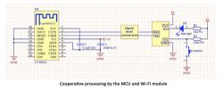
Hello, my dears.
Here I will present the theory and practice of implementing TuyaMCU protocol support. TuyaMCU is a UART-based protocol used to communicate the WiFi module with the main microcontroller of the Tuya device. This protocol is used in many IoT products, including: in dimmers, temperature/humidity/etc. sensors. with an LCD display, in heating and blind controllers and even in household appliances (e.g. Blitzwolf fryer). TuyaMCU support I will program the WiFi module side in C language. I will perform both reading (parsing) of packets and sending them. Code snippets from this topic are part of my OpenBK7231T project available on github .
TuyaMCU - basics
TuyaMCU is a way of communicating a WiFi module (it can be a module with ESP8266, e.g. TYWE3S, or a completely different one, e.g. WB3S with BK7231T) with a microcontroller (e.g. MM32F003). This communication takes place via UART - i.e. two signals, RX to TX and TX to RX. Standard baud 9800.
TuyaMCU allows you to divide the duties of controlling the IoT device into two systems - the WiFI module, which deals with communication with the outside world, and the microcontroller, which usually handles other things (e.g. LCD display, buttons, encoder, dimmer, triac control, etc.) .
Not all Tuya IoT devices use TuyaMCU, because sometimes the WiFi module itself is enough and no additional microcontroller is needed.
There are two operating modes of TuyaMCU. In one case, the WiFi module still has some responsibilities:
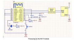
In the second case, most of the things are handled by the microcontroller, and the WiFi module only provides communication:

The diagrams include the conversion of UART voltage levels, but this is usually not needed because both the MCU and the WiFi module operate on 3.3V.
TuyaMCU is a binary protocol, so when we suspect UART communication, we will see "bubbles", it is not `pure-ASCII` that we can read with the naked eye.
Messages sent both ways are divided into packets.
The package structure is identical in both directions:
| Field | Length (bytes) | Description |
| Heading | 2class="notranslate"> | Always the value 0x55AA |
| Version | 1 | The protocol version may change depending on the direction of communication |
| Command | 1 | Type of package (content) |
| Data length | 2 | The size of the packet`s data content in bytes |
| Data | x | Package data, number of bytes given in the previous field |
| Checksum | 1 | Packet checksum in the form of the remainder of adding all previous fields to 256 (I will present the algorithm later) |
Commands include:
| Command | Description |
| 0x00 | The so-called `heartbeat`, i.e. regular communication - reporting that the device is still working |
| 0x01 | Product information inquiry |
| 0x02 | Inquiry about the working status of the WiFi module |
| 0x03 | WiFi connection information |
| 0x04 | A package that resets the WiFi module to a given configuration mode |
| 0x05 | A package that resets the WiFi module to a given configuration mode |
| 0x06 | Setting the device state (e.g. turning on the relay, setting the brightness of the dimmer) |
| 0x07 | Downloading the device status (as above, also for downloading e.g. temperature or humidity) |
| 0x1C | Get the current time for the calendar |
This is not an exhaustive table. Typically, only a few commands are used.
One of the most important commands is 0x06/0x07, it also contains a special data substructure, which is presented below:
| Field | Size (bytes) | Role |
| dpID | 1 | function identifier (device type dependent) |
| Data type | 1 | Specifies the type of data in the package, according to the enumeration presented a little later: integer, enum, string, etc.) |
| Length | 2 | data length |
| Data | x | a field with data of the length specified earlier |
dpID, i.e. the function/variable index, has different meanings depending on the device. If we want to support a given device (e.g. thermometer/hygrometer TH06), it must guess that e.g. dpID = 1 is temperature, dpID = 2 is humidity, etc. etc.
The same with Tasmota - there we also have to provide it manually when configuring the device.
Promised data types:
| Name | Code | Description |
| DP_TYPE_RAW | 0x00 | No specific role |
| DP_TYPE_BOOL | 0x01 | A byte representing boolean (true or false) |
| DP_TYPE_VALUE | 0x02 | A four-byte integer value |
| DP_TYPE_STRING | 0x03 | ASCII string (string). |
| DP_TYPE_ENUM | 0x04 | Enumerator value |
| DP_TYPE_BITMAP | 0x05 | Bitmap (image) |
In theory, the TuyaMCU protocol requires initialization by reporting the version and operating mode of the device, but in practice it seems to me that this is not necessary - neither Tasmota nor my firmware at the moment performs full negotiation with the microcontroller, we basically only send and download immediately data.
Below is a state diagram of TuyaMCU according to: Tuya:
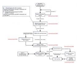
A little later I will present the captured TuyaMCU packets (right after the device is turned on), the order of which matches the diagram.
TuyaMCU - example of a dimmer on TYWE3S
Let`s look at the first example product divided into a WiFi module and a microcontroller. It will be a WiFi-controlled dimmer, WF-DS01:
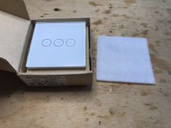
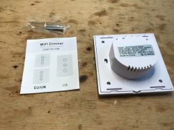
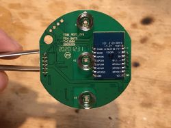
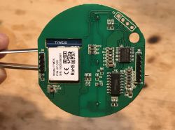
Diagram:
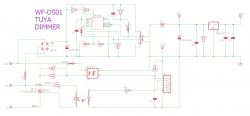
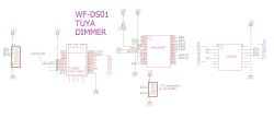
Inside there is TYWE3S (WiFi module with ESP) and the MM32F003 microcontroller. We also have a third chip here that supports touch buttons.
For more information about this dimmer (and a description of the procedure for uploading Tasmota), please click here:
https://www.elektroda.pl/rtvforum/topic3825966.html
TuyaMCU - example of a dimmer on WB3S
A slightly different dimmer - EDM-01-AA-EU KER_V1.6. In previous versions it was implemented on RTL8710BN, now it is on WB3S. Photos from inside:
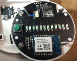
The diagram, sketched by me:
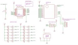
Inside is SC95F861X:
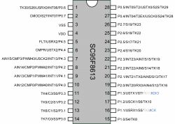
Here we see that SC95F861 takes care of practically the entire lighting control - the RESET button is connected to it, diodes 1-12 showing the lighting level, the zero detection signal for the dimmer and the triac control itself (called PWM in the diagram) are connected.
TuyaMCU - clock/thermometer example - TH06
The third example of a device using TuyaMCU could be the TH06 clock/thermometer/hygrometer/calendar:
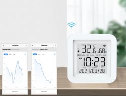
The microcontroller inside is not signed and the WiFi module is WB3S. The large chip in the middle is the TM1621B display controller.
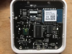
For more details about TH06, please refer to the topic:
https://www.elektroda.pl/rtvforum/topic3819498.html
Regardless, I`ll stop here. I will use the TH06 as a hands-on demonstration.
You need to start by capturing packets.
We capture packets by simply connecting the RX line of our UART converter, first to TX and then RX from the board (both lines work).
TuyaMCU uses baud 9800.
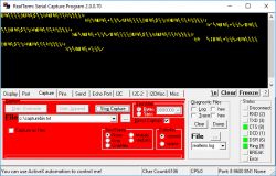
On the computer side I use RealTerm and the Capture option:
We can analyze the collected data in a free hex viewer program, e.g. xvi32, or in the RealTerm options set it to save bytes as ASCII (human readable) and then all you need is a notebook:
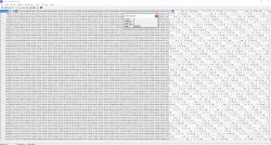
It`s easy to get lost in such a large number of bytes. For convenience, I transferred the results to Word, where I could color the background of individual data sections, i.e. highlight the heading, type, length, checksum and so on:
This is how I collected the entire "conversation" between WB3S and the microcontroller, data in both directions. I will analyze them in the next paragraph.
TH06 - package content in practice
I collected the packets shown below just after the device was booted up so that they also included the initial negotiation and the microcontroller descriptor packet.
NOTE: I have omitted some lesser known (less important) types of packages here. Full communication in the .doc attachment.
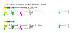
First, the WiFi module sends `heartbeat` and the MCU responds to it:
Then the WiFi module sends "Query product information" and the MCU responds to it:

The response from the MCU contains ASCII text, more precisely in JSON format:
{"p":"7akwzwfwhukkdsib","v":"1.0.0","m":0}
Then the WiFi module sends "Query WiFi information":


The answer to this also includes the roles of the pins (where is RESET, etc.).
Then the WiFi module asks about the device status, and more specifically about the temperature and humidity readings (done by the MCU):

Several packages may come in response to this. In the case of this device, three came, I will show two of them here:
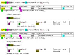
The temperature information obtained in this way is then sent to the Tuya cloud, so you can also create graphs, read them remotely, etc.
There is still communication in the other direction - the time is downloaded by the WiFi module from NTP servers and sent to the MCU in the following packet:

UART - data reception circular buffer
At this stage, we begin to fully practice and program. We will write a program for the WiFi module, i.e. the same as WB3S or TYWE3S (ESP8266). But basically a UART circular buffer is necessary on both sides.
The buffer is involved in the process of receiving data from UART. The UART interrupt passes character by character to the buffer, and we empty the buffer from the external function when the entire packet is collected in it. The data in the circular buffer loops (hence its name), and its length should be much larger than the length of the entire packet we expect to receive.
When reading from the circular buffer, we should disable e.g. UART interrupts (or use a mutex).
What does it take to describe such a buffer?
Four variables are needed:
- buffer itself (byte array)
- the size of this array
- index of the "in" character, input, i.e. where we will enter the next character received from UART
- index of the output character, "out", i.e. where we have the cursor reading data from it
Code: C / C++
NOTE: of course, depending on the language we write in (C++ or C), it is worth considering packing it into a structure or class.
Buffer initialization is simple - it allocates memory to the buffer and sets the cursors:
Code: C / C++
I have divided adding to the buffer into two functions, this is what triggers the UART interrupt when we receive a character:
Code: C / C++
The condition in the nested if loops the index when we reach the end of the buffer. The first if checks whether there is still space in the buffer (if it does, it frees it, then it "loses characters", the >= condition is a bit of an exaggeration because it is impossible for the buffer to contain more characters than its full size). test_ty_read_uart_data_to_buffer is invoked from the UART interrupt.
And functions that allow reading from the buffer:
Code: C / C++
Separately divided into retrieving the current size of the buffer (difference between the writing and reading cursors, looped), `suspecting` a given byte in the buffer starting from the reading cursor and `consuming` (skipping) the N bytes that we have probably read earlier.
We will use these functions in the next paragraph...
Basic packet parsing and invalid data rejection
We already have a circular buffer, but we don`t know yet how to detect the entire packet. We need to know where one section of data begins and ends.
For this purpose, it will be useful to know the package structure and its identifier (0x55AA).
This is what the function executed periodically in a loop by the main program looks like:
Code: C / C++
We see the following operations here:
- the function skips the `garbage` that is before the header of the next packet, i.e. 0x55AA (two bytes)
- the function checks whether the entire package is already available in the buffer (constructs its length from the len fields - two bytes - its data)
- if there is already a whole package, the function copies its data `outside` and consumes bytes from the circular buffer
Feature Usage:
Code: C / C++
The TuyaMCU_ProcessIncoming function can be implemented below, its argument is basically the entire TuyaMCU package already separated.
Code: C / C++
The function above primarily consists of security features including:
- checking the packet header
- checking whether the length declared in its data is consistent with the actual length
- counting and checking its checksum (if there were no interferences, if there was no "bit flip")
Additionally, it then determines the packet type and, using the switch block, selects appropriate packet handling functions (e.g. device state).
Sending information to your device
All packages have the same basic structure, so we can send them using one function, which, among others:. incl. will automatically calculate the checksum of the data and place the values in the appropriate fields (e.g. package type):
Code: C / C++
"payload_len" is treated specially because it is of the `word` type, a two-byte word, and we have to split it into bytes. The checksum is calculated very simply and uses a byte overflow.
Sending information to the device (example of sending date/time to the display)
Basically, I have already shown such a package in the paragraph devoted to the analysis of intercepted communication with TH06.
This is what the function that creates it looks like:
Code: C / C++
Example of use:
Code: C / C++
Result:
Device status packet
A device status packet requires slightly more processing than a regular packet. The device status includes, for example, reading temperature, humidity, status of relays, buttons, etc. etc. State variables have unique indexes (dpID) that I mentioned at the beginning, and additionally have types (DP_TYPE_RAW, DP_TYPE_STRING, etc.) and data sizes.
In theory, one status packet can contain several variables, but in TH06 it is split into three packets (one variable each).
Here is the function that parses such a package:
Code: C / C++
At this point, this function only displays the acquired information and does not process it further. Despite this, it is able to correctly "extract" temperature and humidity from TH06, which I tested in my batch for BK7231T (OpenBK7231T).
First, however, I need to manually send a query about the device status (the screenshot shows the web panel from the WiFi module):
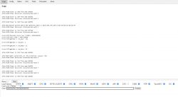
Then I receive 3 packets, temperature and humidity values marked in the screenshot:
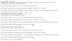
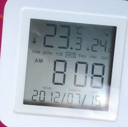
230 or 23.0 degrees and 24 (% humidity). This is consistent with the readings from the display (well, the temperature had already changed by a fraction of a degree before I took the photo):
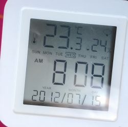
In this way, we can both send and receive data via TuyaMCU. We are able to read the device status and set it.
Summary
Knowledge of the TuyaMCU protocol may be useful in various situations - both when we want to configure our device to work with Tasmota (when implemented on ESP8266) or with my firmware (when implemented on BK7231T/BK7231N/XR809), as well as when we want to write our own firmware for such products or modify existing ones (TuyaMCU is easy to run on ESP without any additional bells and whistles, there are even projects of this type on github, e.g. WThermostatBeca ). This can help us make the purchased device independent of the manufacturer`s servers, add more functionality to it and connect it to devices from another ecosystem with which it was not normally compatible.
I will continue to develop my TuyaMCU implementation, it is not the final version, and in addition I omitted several issues in the article (e.g. disabling interrupts/semaphores that are in the Tuya SDK - see tuya_common/src/driver/tuya_uart.cz tuya-iotos-embeded-sdk- wifi-ble-bk7231t).
Additional materials:
- repository of my batch for BK7231T and similar (that`s why I implemented TuyaMCU)
- topic about my BK7231T firmware
- TuyaMCU library for Arduino
- Tasmota documentation about TuyaMCU
- my Home Assistant tutorial
- my Tasmota tutorial
- "Getting started guide" from Tuya
- TuyaMCU support source code from Tasmota
[i]I am attaching my .doc file with captured TH06 packets (some decoded, some not).
Cool? Ranking DIY Helpful post? Buy me a coffee.


