logo elektroda
logo elektroda
X
logo elektroda

How to check the electromagnetic relay? One way

tomybb 17268 37
ADVERTISEMENT
Treść została przetłumaczona polish » english Zobacz oryginalną wersję tematu
📢 Listen (AI):
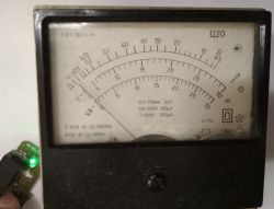
  • Analog pointer meter measuring voltage at the relay module output, with a green LED visibly lit.
    Some time ago there were several articles on our forum about basic issues, min. <br/span> Some time ago, there were several articles on basic issues in our forum, including "How to check a fuse?", and although several people thought that the subject was too obvious, I would argue that .... maybe not quite. I believe that people, even those working in the industry, often get "lectured" on this very type of measurement.... My article today will focus specifically on the relay and how not to be fooled yourself when checking it. The situation was excellent because I had just such a faulty component. Nothing was simulated here. So I thought I would present and describe the situation.

    Of course, I am talking about electromagnetic relays, which are widely used in a variety of electrical, electronic and automotive equipment. It should be remembered, however, that there are also other designs, but not about that now.

    As for the basics, principles of operation, markings, symbols - I refer to the literature, the Internet or even our forum:
    https://www.elektroda.pl/rtvforum/topic3102772.html

    Here we focus only on how to check such an element.

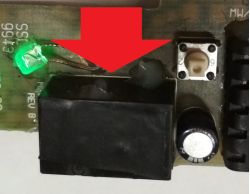
    And then there is our defective hero of the episode. A small relay in a black housing. Mounted on a PCB, this is the module from the car. Pressing the momentary tact switch visible on the right switches on the relay's operating contact, which applies 12V to the module's output. Another press switches it off. I deliberately do not show the whole circuit, how it is controlled etc. as I want to show, on this particular example, the operation, behaviour of the damaged relay itself . The green LED does not have any meaning here, please do not be confused by it :) .


    Close-up of a black relay mounted on a PCB, highlighted by a large red arrow pointing at it.
    .

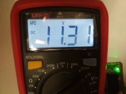
    We start the test, module driven, multimeter connected at the output, like a receiver. When switched on, full voltage appears, as if everything should be working. Voltage a little below 12V because the whole circuit was powered from just such a voltage.


    UNI-T UT33D+ multimeter display showing a DC voltage of 11.31 V.
    .

    Well, maybe a more expensive multimeter will detect some anomalies? Check out the video to see what it looks like with the Sanwa.


    Everything looks as it should all the time...

    How about an old analogue multimeter?


    .

    None of the instruments showed any abnormalities....

    LED with resistor? In the video below, the green LED on the left connected in series with a resistor, plugged into the output, as a receiver.


    .


    Nothing of the methods so far has caused the relay to fail. And let me remind you that it is faulty! :) .

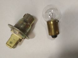
    And an ordinary 12V low-power bulb?


    A car light bulb and its socket lying on a white background.
    .

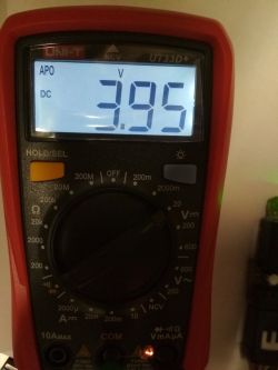
    In this case finally something starts to happen, The output voltage drops, it does not reach 12V, the bulb does not light up completely, it dims.


    UNI-T UT33D+ multimeter display showing a reading of 3.95 V DC.
    .


    .

    Only the last test showed the damage. The working contacts of the relay may be responsible for this symptom, which qualifies the relay in its entirety for replacement. This article was intended to show that sometimes just checking with a multimeter or suggesting the LED indication is not always correct. In a case like this, the test must be performed under load. Traditional incandescent lamps with a voltage and wattage adapted to the component under test are ideal for this purpose.Sometimes flickering, dimming, incorrect operation of the receiver can be observed immediately. The use of too high a load can only do harm here; too low a load will not always reveal the fault. Finally, I would like to remind you that we were operating at around 12V here, so you can afford such experiments; if you are checking components at e.g. 230V, do not do such tests for safety reasons!

    Cool? Ranking DIY
    About Author
    tomybb
    Level 26  
    Offline 
    tomybb wrote 1708 posts with rating 1766, helped 3 times. Been with us since 2006 year.
  • ADVERTISEMENT
  • #2 21540543
    tos18
    Level 42  
    And measuring the contact resistance with an ohmmeter?
  • #3 21540546
    Baskhaal
    Level 19  
    Here, it is a situation where the working contacts of the relay form an electrical contact sufficient for small currents but, due to a manufacturing defect (or mechanical damage or corrosion, etc.), at higher currents begin to slightly deform, heat up, "flicker" like, for example, a bimetal.
  • ADVERTISEMENT
  • #4 21540547
    sigwa18
    Level 43  
    In measuring automotive installations, I learned a long time ago to test the voltage (especially of the power supply) under load or with the module sensor attached (inserting needles from the back of the plug). This is the basis for diagnosis.
  • #5 21540630
    tomybb
    Level 26  
    tos18 wrote:
    A contact resistance measurement with an ohmmeter ?
    .

    An ohmmeter causes a small current to flow so it could also fail at such a fault. It doesn't put a load on our relay contacts. How many times has something that appeared to work on an ohmmeter failed in the circuit? Here quite similar to checking the fuse with an ohmmeter, a topic I alluded to at the beginning.

    You might be tempted to measure with a precision milliohmmeter, perhaps a four-wire measurement....

    However, I have not had the opportunity to carry out such a test here....

    It seems to me, however, that measurement with a properly selected bulb is simpler and more reliable.
  • ADVERTISEMENT
  • #7 21540700
    CosteC
    Level 39  
    And in addition, this is only the beginning of the types of relay failures. Almost nothing can be detected with a multimeter.
    It is a pity that the author of the post did not show how much the contact resistance is measured with an ohmmeter and how much it is under load.
    It would have been nice, also to see what such damaged contacts look like. Not for nothing do many relays have transparent housings.
  • #8 21540749
    klamocik
    Level 36  
    This subject has already been discussed in the past, we had one at work, but it was even 4 NO and NC contacts and the indicator was the light bulbs. Hundreds of different relays were checked during the overhaul.
  • #9 21541008
    Jacekser
    Level 26  
    Experienced electricians have long since established that voltmeters (~multimeter) with a high input resistance are not suitable for testing current circuits. Electric installations exposed to moisture and dust can distort the voltmeter test. They simply test the circuit with a light bulb.
  • #10 21541013
    sigwa18
    Level 43  
    Two incandescent lamps of the same wattage connected in series are better. At 230 volts they will also light up (less brightly, of course), but there is no risk of them blowing up when connected to two phases (400 volts).
  • #11 21541014
    Jacekser
    Level 26  
    sigwa18 wrote:
    It is better to have two incandescent lamps of the same wattage connected in series. At 230 V they will also light up (weaker, of course) but there is no risk of them blowing up when connected to two phases (400 V).

    Don't hint! Let them think. ;-)
  • #12 21541143
    rosomak19
    Level 23  
    As mentioned above , I would start by measuring the coil resistance (for continuity) before applying voltage, and measuring the contact resistance after applying voltage to the coil .
  • #13 21541368
    DJ_KLIMA
    Level 24  
    The bulb should always be the classic for checking current circuits, good current rise, great limiting at the same time, and also visual inspection.
  • #14 21541681
    Ktoś_tam
    Level 39  
    tomybb wrote:
    tos18 wrote:
    And measuring contact resistance with an ohmmeter ?
    .
    An ohmmeter causes a small current flow so with such a fault also could fail .
    .
    tomybb wrote:
    In a case like here the test must be performed under load.
    .
    It's a pity that you didn't check it, maybe it would have turned out that even a meter for a dozen or so zloty would have been able to cope, and the whole article about how intelligent you are and using little-known methods of diagnosis is pointless in this case.
    Trust me, I've already replaced a relay or contactor more than once by measuring its contacts, i.e. its resistance with an ohmmeter using a low current, and trust me, this method worked.
    I am not denying your method, because it is a good one. However, the claim that the most expensive multimeter cannot handle it is wrong. Resistance measurement may not always work, but it hasn't failed me yet.
  • #15 21541720
    cranky
    Level 28  
    Yes, and no.
    I just had a problem where relays were switching 4 circuits, some of which were switching some small but nonetheless loads, and some of which were providing a signal to the controller (i.e. from PLC to PLC as a confirmation of operation). And it was these contacts that had become so oxidised (because I don't think they were dusty) that they were not supplying voltage. The flowing current was burning through/piercing the oxidised layer on the contacts. And these contacts, through which the current flowed close to zero - stopped contacting.
    The conclusion is that it is better to first check with a meter and then check with a load (because these contacts "weathered" when connected to an incandescent bulb would rather "revive").

    The second case was with miniature electromagnetic relays after running about 4 million bars. They started to fail to catch once every few hundred times. No measurements indicated any problems, and upon disassembly I also found no signs of damage either electrical or mechanical.
    The conclusion is that if the application requires reliability, then whatever the result, 2 million switching and retirement can be assumed.
  • #16 21541790
    maly310
    Level 12  
    >>21540475 Hello, I had a similar case but with a power amplifier i.e. every now and then the volume in one channel would drop and there was a slight crackle. I replaced the input potentiometer, checked all the solders until finally I left the amplifier open for a couple of days and waited for the mentioned sound effects. As soon as I noticed the muted sound I immediately put a screwdriver in my hand and "tapped" every component from transistor to capacitor until I found the relay. I cleaned the contacts of the relay on a test basis and in over a month I have not noticed any crackling or loss of volume. Eventually a new relay will be inserted in the protection board.
  • #17 21541806
    sanfran
    Network and Internet specialist
    Similar situations happen in old cars (yes more than 30 years old). The insulation in the wires loses elasticity and they like to break most often at the connectors. In this case, the multimeter will not detect the problem either. However, when such a cable is loaded with several amperes (a 21W bulb is almost 2A), miracles begin to happen, especially when the engine is running, which introduces vibrations and causes additional problems.
  • #18 21541823
    sigwa18
    Level 43  
    Sometimes even the plugs themselves make bad contact. A common problem in VAG throttle plugs. Apparently everything is ok and the contact on the connector is poor. The same applies to the wires, which can also become infected with the green stuff. A light scratch to the insulation is all it takes, and water and road salt do the rest. The cable seems to be intact, but half of it is green powder instead of copper.
  • #19 21541854
    tomybb
    Level 26  
    A few words of explanation...

    In writing this article I can now see that I made a small mistake. I focused on one case of mine that happened to me during a repair. Because I wasn't set on writing the article at that moment, I didn't think of everything; if I had prepared in advance and planned what else was worth checking, I would certainly have taken that unfortunate ohmmeter measurement and included photos of the contacts (because I had smashed the very, undisassembled housing of this relay). And so this, the article, was written as it were on another repair, the module had to be repaired quickly and there was no time to go back. I don't know if I still have this replaced, damaged relay left somewhere, maybe if I could find it I would dispel doubts.

    As for measuring the coil and operating contacts with an ohmmeter, of course!, we should do that first, while I have pulled it up in those basics I haven't mentioned anything about here. As well as about the construction of the operating principle etc. I can see now that not mentioning it was a small mistake after all,. On the other hand, I wanted to emphasise that measuring with an ohmmeter will not always be reliable, in many cases it will be enough, but in some cases it will not and can only cause us problems....

    An interesting example was given by a colleague

    cranky wrote:
    The flowing current burned/pierced through the oxidised layer on the contacts. And those contacts through which the current flowed close to zero - stopped contacting.
    The conclusion is that it is better to first check with a meter, and then check with a load (because those contacts "weathered" when connected to an incandescent bulb would rather "recover").


    I agree, in such a case as absolutely the first resistance measurement. I concentrated on my case and not on any relay in general, in my case it switched higher currents, so I used a load comparable to the load at which it actually operates. I only mentioned briefly to select a suitable load when checking. However, if one were to be 100% precise one would have to write that: first check the contacts with an ohmmeter (at low current), if the measurement is correct check under the rated load. I guess that would be 100% correct then.


    Ktoś_tam wrote:
    Trust me, it has happened to me more than once to replace a relay or contactor by measuring its contacts, i.e. its resistance with an ohmmeter using a low current, and trust me, this method has worked.
    .

    I don't have to trust you because I myself know very well that in many cases this is enough, maybe even in most cases. On the other hand, trust me now, there will be a time when the same ohmmeter measurement can get you lost. As I mentioned before, it is best to check first with an ohmmeter, if there are any anomalies here then there is no need to check further, but if the ohmmeter indicates 0 it does not necessarily mean that we have a 100% working component.


    Ktoś_tam wrote:
    tomybb wrote:
    tos18 wrote:
    And measuring contact resistance with an ohmmeter ?
    .
    An ohmmeter causes a small current to flow so it could also fail with such a fault.

    tomybb wrote:
    In a case like here, the test must be performed under load.
    .

    in both my statements that you quote I used the key words: "could" (does not mean definitely), and "in this case"

    let me remind you again that all along I was referring specifically to the example I had.

    Ktoś_tam wrote:
    It's a pity that you didn't check it, maybe it would turn out that even a meter for a dozen or so zloty would cope and the whole article how you are intelligent and use little known methods of diagnosis are in this case pointless.


    First of all "a meter for a dozen zloty" is certainly not a good idea.... especially when it comes to measuring small resistances - the probes themselves (the tips are made of steel and not, for example, brass) mean that when they are short-circuited, we may not see 0 Ohm on the LCD, but sometimes a fluctuating value of several Ohms. (also depending on the pressure, the appropriate "sticking" into the test object, etc...). Here, if you already have, you would have to equip yourself with at least some better probes.... but then it would no longer be a dozen or so zloty for the whole thing....

    And finally, this biting and spitefulness on your part, please tell me where it comes from?
    Do you think I want to exalt myself with this article? Is that why I am writing it? That I am smarter than someone? I really don't know where this comes from in people, sometimes you just get discouraged from posting anything. Can't you make your points like the rest of the commenters here just have to be alluding to me? I don't consider myself the smartest at all, on the contrary, I'm learning something all the time, including here....

    I did not say anywhere that I use unknown diagnostic methods, I only drew your attention to a certain problem which may happen to anyone at some point, and I myself have encountered more than once a situation where people working in a similar field judge the correctness of a relay's operation by just hearing a "click" or signalling the presence of voltage on the coil (or on the output) using an LED.

    So much for.
  • #20 21541908
    stasiekb100
    Level 29  
    tomybb wrote:
    You might be tempted to measure with some sort of precision milli-meter, maybe a four-wire measurement..
    .
    That's what you've done in this video. To improve it, use a 1A current source instead of an incandescent bulb.
  • #21 21541910
    acctr
    Level 38  
    I think there was a lack of summing up and drawing conclusions, especially as you had a specific faulty unit at your disposal.
    Claiming that you cannot check it with a multimeter, but with a light bulb you can, is making electrical engineering a field where there is some kind of secret knowledge and magic.
    If a contact does not work because it has a high resistance, you could at least try to show whether it meets Ohm's law or not.
    Helpful post? Buy me a coffee.
  • #22 21541977
    Ktoś_tam
    Level 39  
    What pinches? I didn't negate your method, but the statement that the most expensive multimeter can't handle it. With such a voltage drop as yours, the resistance is large enough that a multimeter for a dozen or so zlotys can handle it, while a meter that shows a few Ohms with the probes shorted is suitable for the PSZOK, although it might be possible to measure such a large resistance with it.
    By the way, relays that were 0.1 or 0.2 Ohm above the manufacturer's specifications ended up in PSZOK because the device did not work properly. Your current method is unlikely to work in diagnosing such a resistance, but an inexpensive meter, for a couple of hundred, will, as long as it shows the resistance at 2 full Ohm positions.
  • #23 21542071
    max-bit
    Level 34  
    In fact, to assess a relay you need to see the condition of its contacts.
    Otherwise, heck knows what their condition is. Otherwise it's just speculation.
    The contacts may have low resistance or they may already be burnt.
    Also, there are different relays for different applications and, among other things, the alloy from which the contact is made will be different for DC, different for AC, different for low current, different for high current and still different for low signal applications.
  • #24 21542827
    cranky
    Level 28  
    acctr wrote:
    If the contact doesn't work because it has a high resistance then you could at least try to show if it obeys Ohm's law or not
    .
    I wish you luck in checking ohm's law on a sparking contact. Some oscilloscope and integration of "delta dirac" signals?
    max-bit wrote:
    In fact to evaluate a relay you need to see the state of its contacts.

    First of all, a fair amount are undisassembled. Although the "since I took it apart, it's replaceable" method is always effective. :) .
    In addition, a mechanically molded one does not necessarily have bad contacts. It may be blocking in another location. It may have a "shortened coil", making it react differently than it should....
  • ADVERTISEMENT
  • #25 21542895
    acctr
    Level 38  
    cranky wrote:
    I wish you good luck checking ohm's law on a sparking contact. Some oscilloscope and integration of "delta dirac" signals?
    .
    As one does not understand Ohm's law one is left with checking the Dirac delta :D
    Helpful post? Buy me a coffee.
  • #26 21542969
    puchalak
    Level 17  
    If a relay is working in some device, switching on a particular load, it makes the most sense to test it in that circuit by measuring the voltage drop across the contacts when it is switched on, possibly removed, loaded with an equivalent current, or the rated current provided for it. A not very sophisticated voltmeter is sufficient for this. A test current of 0.5 or 1A for a relay operating with a 100A load is not authoritative.
  • #27 21543046
    cranky
    Level 28  
    puchalak wrote:
    for a relay operating at 100A
    .
    100A is a contactor not a relay. And here's an interesting fact - a three-phase contactor does not energise one phase on three consecutive starts. On the fourth it starts normally. The voltage drop on the suspect phase is 7VAC.
    Upon disassembly, it turns out that the contacts are so stoned that physically the plates do not touch! However, the electric arc when ignited has a very low resistance and the voltage drop is negligible.
    For contactors, the best method is thermal imaging.
  • #28 21543056
    sigwa18
    Level 43  
    Thermal imaging inspections of control and power supply cabinets are probably already standard.
  • #29 21543272
    puchalak
    Level 17  
    cranky wrote:
    puchalak wrote:
    for a relay operating at 100A
    .
    100A is a contactor not a relay...
    .

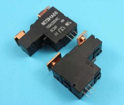
    This is a somewhat conventional issue. There are 70A relays in cars and they are not called contactors. The circuits in my house switch 100 - amp bistable relays (they are sold as such) such as the one below in the photo only with coils for 12V.
    Two black bistable power relays marked NE2101-A1-5D with copper terminals and pins, lying on a blue background. .
  • #30 21543279
    sigwa18
    Level 43  
    Glow plug relays in cars and trucks are approved for 100A and above. I was taught that the contactor has an arc quenching function i.e. working with inductive loads.
📢 Listen (AI):

Topic summary

The discussion focuses on methods to check electromagnetic relays, emphasizing the limitations of using an ohmmeter alone due to its low test current, which may not reveal contact faults such as corrosion, mechanical damage, or oxidation that manifest under load. Measuring contact resistance with an ohmmeter can indicate continuity but often fails to detect issues that appear only at higher currents. Testing relays under load using incandescent bulbs or specialized testers (e.g., Testboy) provides a more reliable diagnosis by simulating real operating conditions and revealing contact degradation through voltage drop or flickering. Visual inspection of contacts, especially in relays with transparent housings, is also important. The coil resistance should be measured first to confirm coil integrity. Some relays have gold or platinum-plated contacts to reduce oxidation and improve longevity. Thermal imaging is recommended for contactors and high-current relays to detect overheating contacts. The discussion also notes that relay failures can be intermittent and that testing in the actual circuit with appropriate load current is often the most effective method. The importance of understanding relay specifications, such as minimum or self-cleaning current, is highlighted for proper testing and maintenance.
Summary generated by the language model.
ADVERTISEMENT