Elektroda.com
Elektroda.com
X

ZN268131 WiFi Smart Switch that allows you to connect a bistable button

p.kaczmarek2 8421 41
This content has been translated flag-pl » flag-en View the original version here.
  • ZN268131 WiFi Smart Switch that allows you to connect a bistable button
    I will show here a slightly less typical type of WiFi transmitter, which allows you to use the bistable button you had previously to control the device. I will also show how you can convert any other kind of smart switch to work with external bistable button by using OpenBeken.
    Classic sonoff-type IoT relays have only a small momentary button (monostable) on the housing, so you can't reuse existing bistable button for a lamp. Of course, leaving its switch in front of the intelligent relay will not do you any good, because if it was turned off by its button, the relay would not work anyway.
    To be clear - the bistable button has two states in which it stays in when you switch it (it stays on "On" or "Off"), and the monostable one has one constant state, when you press it, it always returns to the first state when released.
    There is, however, a good solution to this problem - just connect the aforementioned bistable button to our smart relay and handle it in the program code in such a way that the change of its state resulted in a change of the relay state . It is convenient because then you can also change the status of the relay via WiFi. The only thing that will change then is that the "On" and "Off" positions on the bistable button will lose their importance then, because its actual position will not matter for the controller, only the act of switching it.
    Of course, there are ready-made solutions for this that work with the Tuya application, but here I will present the use of such a relay together with my open firwmare for Beken family deals . This will ensure independence from the manufacturer's servers, security and anonymity (the cloud will not start collecting data when you use the devices). In the topic I will also attach some details about the implementation of such a switch in C code.
    In addition, I will discuss flashing OpenBeken to WB2S module here again, because in this particular case of the relay there is a problem with it - you will have to cut one trace.

    CAUTION
    The relays described here operate on a deadly mains voltage potential. In addition, most relays of this type only cut off one wire (there is a single relay), and it depends on the user which one, so it is possible that unfortunately you will cut the neutral and the live will be permanently connected to the controlled device ... I assume that the reader will tell you about this knows everyone and is aware of how to connect everything electrically according to the art. Here I will focus on programming smart switches.
    In addition, it is also worth remembering that often the power supplies from such gadgets are also not separated (and e.g.. there may be a phase potential on the GND connected to the WB2S).

    Purchase and interior of ZN268131
    I bought ZN268131 from one of the websites selling online. It is quite a popular product. It can be found even after 20-30 PLN with free shipping. It is not always marked with the symbol I am showing here.
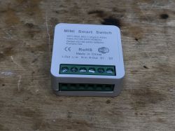
    ZN268131 is distinguished by the presence of a screw terminal for the switch - they are labelled S1 and S2.
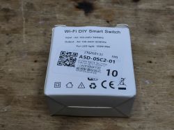
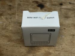
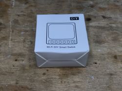
    It comes in a box like this:
    ZN268131 WiFi Smart Switch that allows you to connect a bistable button ZN268131 WiFi Smart Switch that allows you to connect a bistable button ZN268131 WiFi Smart Switch that allows you to connect a bistable button ZN268131 WiFi Smart Switch that allows you to connect a bistable button
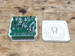
    To upload the firmware, remove the plastic cover:
    ZN268131 WiFi Smart Switch that allows you to connect a bistable button ZN268131 WiFi Smart Switch that allows you to connect a bistable button
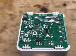
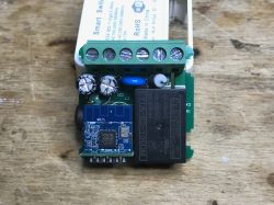
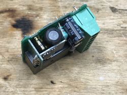
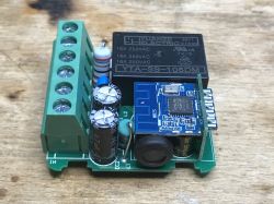
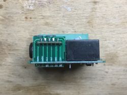
    From the bottom you see the 5V transformerless power supply (AP8506), behind it there is a 3.3V LDO regulator providing a stable 3.3V for the WiFi module, then the (KEY1) button, connection of the board with the WiFi module (only 5 signals go there, actually 3.3V, GND, output to the relay (through Q1 transistor) and two inputs - one for the large bistable button, the other for the small one on the housing.
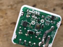
    After removing, you can see the WiFI module (WB2S or BK7231T, I don't know why without a metal case this time), there are also some protections (fuse resistor F2, blue varistor) and a filter on the input (two electrolytic capacitors, EC1 and EC2, and a choke between them) ):
    ZN268131 WiFi Smart Switch that allows you to connect a bistable button ZN268131 WiFi Smart Switch that allows you to connect a bistable button ZN268131 WiFi Smart Switch that allows you to connect a bistable button ZN268131 WiFi Smart Switch that allows you to connect a bistable button ZN268131 WiFi Smart Switch that allows you to connect a bistable button

    Programming ZN268131
    Never attempt to power the relay from mains and flash it at the same time! Power it separately, via 5V connected before AMS1117:
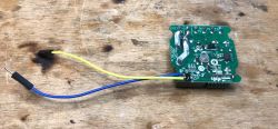
    ZN268131 WiFi Smart Switch that allows you to connect a bistable button
    In addition, only the RX and TX need to be connected to the WB2S pins:
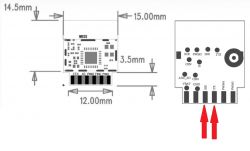
    ZN268131 WiFi Smart Switch that allows you to connect a bistable button
    Initially, I tried to do this:
    ZN268131 WiFi Smart Switch that allows you to connect a bistable button
    Unfortunately it did not work. It quickly turned out that the RX pin is also used here as a button and the pull up resistor on this signal interferes with the programming.
    The solution is to temporarily cut the track so that it can be easily repaired and clip on the WB2S side:
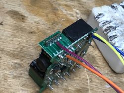
    ZN268131 WiFi Smart Switch that allows you to connect a bistable button
    These 4 cables are enough.
    The rest of the programmer is a USB to UART converter in 3.3V mode and a separate power input (I can not take 5V from USB, because to reboot the device I have to connect and disconnect the power, and when I use USB for this, the relay will take too much current and USB from the USB will reset and the USB to UART converter will be "lost" and the programming will fail):
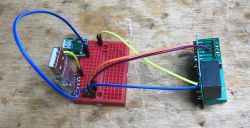
    ZN268131 WiFi Smart Switch that allows you to connect a bistable button
    Programming procedure:
    1. in bkWriter 1.60 select the batch, start programming
    2. while waiting, disconnect and connect the 5V power supply to reboot
    3. the module should program itself without errors
    This is for the BK7231T - for the BK7231N use a Python programmer.
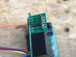
    After programming, fix the cut path:
    ZN268131 WiFi Smart Switch that allows you to connect a bistable button

    OpenBeken configuration for ZN268131
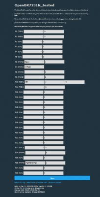
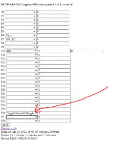
    I have already described the entire configuration procedure for OpenBK7231T several times. Here I will only show you how to configure the "magic" pin from the bistable button:
    ZN268131 WiFi Smart Switch that allows you to connect a bistable button
    That's all - just set the ToggleChannelOnToggle role. The role of "Button" is for momentary buttons.

    For the curious - in the code of the ToggleChannelOnToggle program it is organized very simply, it uses the same timer as regular buttons, and also eliminates the problem of debouncing (contact vibration):
    Code: c
    Log in, to see the code

    Calling the CHANNEL_Toggle function switches the channel value (here: relay). In OpenBK it is possible to map multiple outputs to one channel.

    Test circuit
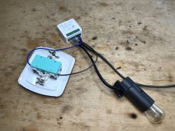
    From now on, you can control the relay with any classic toggle switch, for example one from the box:
    ZN268131 WiFi Smart Switch that allows you to connect a bistable button ZN268131 WiFi Smart Switch that allows you to connect a bistable button ZN268131 WiFi Smart Switch that allows you to connect a bistable button
    Everything works, you just need to get used to the fact that from now on the state of this switch ("pressed down / up") does not determine the status of the relay, because you can always switch externally from the Home Assistant panel.

    A practical example of use
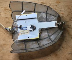
    This time without much comment. For a trial, I connected the module for a rather old and cracked lamp, which I saved from electro-waste:

    ZN268131 WiFi Smart Switch that allows you to connect a bistable button ZN268131 WiFi Smart Switch that allows you to connect a bistable button
    ZN268131 WiFi Smart Switch that allows you to connect a bistable button ZN268131 WiFi Smart Switch that allows you to connect a bistable button
    ZN268131 WiFi Smart Switch that allows you to connect a bistable button


    And can you convert an ordinary Smart Switch to one supporting bistable button?
    With original Tuya firmware it would be not possible, as we don't have access to source code and there is no pins configurator, but with OpenBeken, i t's very simple.
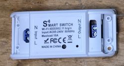
    Just take any Sonoff clone with my OpenBK, for example:
    ZN268131 WiFi Smart Switch that allows you to connect a bistable button
    This one has WB2S inside:
    ZN268131 WiFi Smart Switch that allows you to connect a bistable button
    Quote:

    Pin No. Symbol I/O type Function
    1 VBAT P Power supply pin (3.3 V), which is connected to the VBAT pin on the internal IC
    2 PWM2 I/O Common GPIO, which is connected to the P8 pin on the internal IC
    3 GND P Power supply reference ground pin
    4 PWM1 I/O Common GPIO, which is connected to the P7 pin on the internal IC
    5 1RX I/O UART1_RXD, which is used as a user-side serial interface pin and is connected to the P10 pin on the internal IC
    6 PWM0 I/O Common GPIO, which is connected to the P6 pin on the internal IC
    7 1TX I/O UART1_TXD, which is used as a user-side serial interface pin and is connected to the P11 pin on the internal IC
    8 AD AI ADC pin, which is connected to the P23 pin on the internal IC
    9 PWM4 I/O Common GPIO, which is connected to the P24 pin on the internal IC
    10 CEN I Low-level reset, high-level active (internally pulled high) Docking IC-CEN
    11 PWM5 I / O Common GPIO, which is connected to the P26 pin on the internal IC


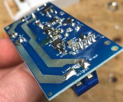
    It is easy to find an unused GPIO. You can see that there are several of them:
    ZN268131 WiFi Smart Switch that allows you to connect a bistable button ZN268131 WiFi Smart Switch that allows you to connect a bistable button

    Bring the wire to it, the other wire to ground. You don't need a pull-up resistor as the BK7231N and T have built-in, configurable pull-ups.
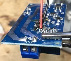
    ZN268131 WiFi Smart Switch that allows you to connect a bistable button
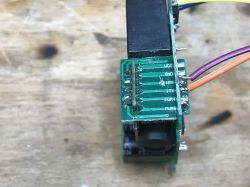
    Lead the wires out of the housing (there will only be 3.3V on them, they do not have to be thick):
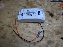
    ZN268131 WiFi Smart Switch that allows you to connect a bistable button
    And it's almost ready - you still need to configure the roles of the chosen pin on the OpenBK web panel and connect the bistable button.
    NOTE - depending on the used relay model and connection, there may be a live potential from the mains on the used wires !!

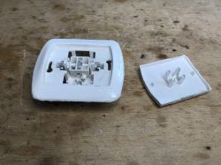
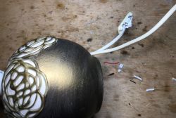
    For example, you can convert an old lamp (yes, also saved from e-waste):
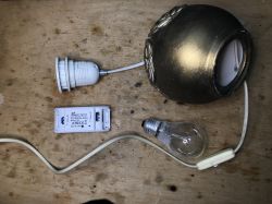
    ZN268131 WiFi Smart Switch that allows you to connect a bistable button
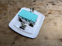
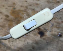
    Use the original switch:
    ZN268131 WiFi Smart Switch that allows you to connect a bistable button ZN268131 WiFi Smart Switch that allows you to connect a bistable button ZN268131 WiFi Smart Switch that allows you to connect a bistable button
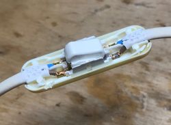
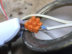
    Connections, additionally I made a joint on a wire so that pulling it by the cord does not tear it out:
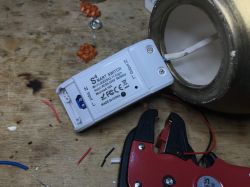
    ZN268131 WiFi Smart Switch that allows you to connect a bistable button ZN268131 WiFi Smart Switch that allows you to connect a bistable button ZN268131 WiFi Smart Switch that allows you to connect a bistable button
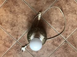
    Ready:
    ZN268131 WiFi Smart Switch that allows you to connect a bistable button
    From now on, the lamp still supports its old button, but it's also smart. For example, you can turn off all the lights (including the lamp) from the Home Assistant when you leave the house.

    What else can the additional button be used for?
    The possibilities are very large. For example, you can remake a simple LED strip controller, such as described here:
    WiFi SmartLife single-color LED strip dimmer - test, interior, diagram
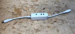
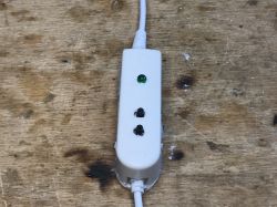
    so that it has two buttons (one for increasing the brightness, the other for dimming) and you can also add an LED to it informing about the WiFi status.
    The buttons increasing / decreasing the brightness of the PWM channel in OpenBeken already require simple scripting, which my firmware also supports:
    
    AddEventHandler OnClick 0 addChannel 1 -10 0 100
    AddEventHandler OnClick 1 addChannel 1 10 0 100
    
    AddEventHandler OnDblClick 0 setChannel 1 0
    AddEventHandler OnDblClick 1 setChannel 1 100
    

    The command syntax is simple. After "AddEventHandler" you have the name of the event (OnClick, OnDblClick, OnHold or other), then the pin index (where the button is) and then the command to be executed.
    "addChannel" adds a given value to the channel with a given index (it can be negative), the last two arguments are the range to which the channel value can change (PWM is from 0 to 100).
    "setChannel" just sets the channel.
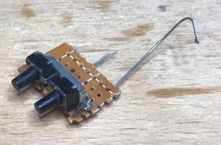
    Really simple, you only need to solder two buttons (even without pull-up resistors because they are automatically configurable in OpenBeken) and a LED with a resistor, give them the Button / WiFi_LED role and add the above script to autorun.bat in the LittleFS file system in OpenBeken.
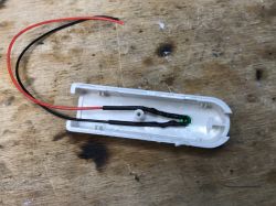
    For convenience, I used the housing from the telephone filter:
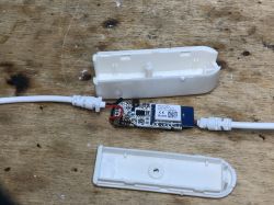
    ZN268131 WiFi Smart Switch that allows you to connect a bistable button ZN268131 WiFi Smart Switch that allows you to connect a bistable button ZN268131 WiFi Smart Switch that allows you to connect a bistable button ZN268131 WiFi Smart Switch that allows you to connect a bistable button ZN268131 WiFi Smart Switch that allows you to connect a bistable button
    Such a modification significantly improves the use of the LED strip that I have in the workshop. The original Tuya firmware only supported turning it on and off with a single button on the housing, and after my modification I have full control over the brightness.

    Summary
    ZN268131 seems to be a very ingenious and convenient gadget, but use of open source software (OpenBeken, unless someone knows an alternative to the BK systems used now? ESP8266 is more and more difficult to find in IoT devices) Makes it possible to take any "regular" WiFi controlled relay and make it work like ZN268131.
    ZN268131 can also be used with original Tuya software, but this has been discussed more than once.
    Of course, when you order Sonoff instead of ZN268131, you can upload Tasmota - but can you, really? Sonoff S40 has already made a "surprise" for users and instead of ESP8266 it has BL602 inside - which by the way I also support in my firmware ...
    PS: And when it comes to my saved from electro-waste and converted lamps, both of them already have their places in the workshop and are used only for long-term tests of my OpenBK batch (I verify the stability of the software, the functionality of reconnecting to WiFi in the event of signal loss, long-term operation of the module without its rebooting, etc.).

    Cool? Ranking DIY
    About Author
    p.kaczmarek2
    Moderator Smart Home
    Offline 
    p.kaczmarek2 wrote 4836 posts with rating 5167, helped 235 times. Been with us since 2014 year.
  • #2
    Szyszkownik Kilkujadek
    Level 37  
    I have one for the desk lamp. It works great. Works stably with Tuya and on original firmware.
    If someone is looking in Polish, it is under the slogan: staircase. If you speak english then: 2-way switch.
  • #3
    kptzbik1
    Level 2  
    Hi there,

    I have ZN268131 working fine with 5V applied to AMS but if I power it up with mains it does not boot.
    Test points have incorrent voltages 3,8(5V) and 2,98(3.3V). I belivie my HW is ok, same issue with 2 different HWs.

    Any idea?
  • #5
    kptzbik1
    Level 2  
    Forgot to mention. This happened after uploading OpenBeken firmware (UA binary). It worked fine with Tuya firmware before.
    is it related to the original bootloader I kept?
  • #6
    p.kaczmarek2
    Moderator Smart Home
    Tuya might have been using low-power mode so the capacitor fault did not manifest itself before. Lower power mode means slightly lower current consumption, it's not added to OBK yet.

    The firmware has no control over the 5V rail, so if you're getting 3.8V on 5V line then there is something wrong with the power supply.
  • #8
    p.kaczmarek2
    Moderator Smart Home
    adampopics wrote:
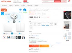
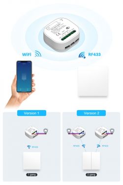
    https://a.aliexpress.com/_EzMhE6x should also work with this guide

    Thanks. In case of link expiration, here are screenshots:
    ZN268131 WiFi Smart Switch that allows you to connect a bistable button
    ZN268131 WiFi Smart Switch that allows you to connect a bistable button
    ZN268131 WiFi Smart Switch that allows you to connect a bistable button
    adampopics wrote:
    the RF chip toggles a WB2S gpio if rhe RF signal matches. Just tested tits pin 8.

    I can confirm that. I've tested such switches about 2 years ago (I've gotten an ESP version that time) and RF433 addition was just injected in a tricky way in the touch button lane. Touch button is connected to both WiFi module input and to RF433 input. That way, a long touch to the button can trigger RF pairing (RF chip monitors the state on button lane), and RF can also toggle the WiFi (RF chip changes it's pin from input to output and then simulates a button touch).

    That's a nice and tricky solution, one could say that this way WiFi chip "doesn't know" about RF chip but it still works. So you don't have to add anything to WiFi module software in order to support RF.
  • #9
    adampopics
    Level 2  
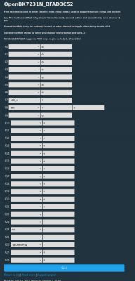
    Here is the complete configuration for the RF three way switch mentioned above:
    ZN268131 WiFi Smart Switch that allows you to connect a bistable button
    The RF switch is even connected to the physical button configuration. Can't seem to be able to figure out the WIFI led part, but it will just be fine in the wall.
  • #10
    zifban19
    Level 2  
    Thanks for the wonderful guide, one question on my side as I was able to do the same with a BK7321N switch: there is now a second delay until the light is turn on/off when using the physical button.

    Do you know how may I fix this? I have tested it with original firmware and it is reacting quite quick.

    Thank you very much for this wonderful guide.

    BR
  • #11
    p.kaczmarek2
    Moderator Smart Home
    Maybe try flag 6?
    Altough flag 6 works for "Btn" role, are you using "ToggleChannelOnToggle"?
    If you are, then flag 6 won't help..
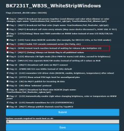
    Quote:

    Flag 6 - [BTN] Instant touch reaction instead of waiting for release (aka SetOption 13)

    ZN268131 WiFi Smart Switch that allows you to connect a bistable button
    ZN268131 WiFi Smart Switch that allows you to connect a bistable button

    PS: IMPORTANT UPDATE! If you are using the cheapest Chinese switches, you might consider adding "PowerSave" command to autoexec.bat or "short startup command" field! This will try to reduce power usage of the device. This is needed because cheapest devices might have so bad power supplies that normal BK7231 activity mode might overheat them or shorten life of capacitors, etc etc.

    Yes, we already have a PowerSave in OBK, also working on W600 etc platforms, and according to user reports it might be helpful on some devices
  • #12
    zifban19
    Level 2  
    Thanks for the suggestion,

    I am using the ToggleChannelOnToggle option so it makes no effect (I tested it too...)

    Thank you in any case, I would try to play a bit more with the device an options, I bet it is something I am missing.

    Thanks for the update related powersave, it is activated now on my devices, not sure if they are the cheapest but if not... close enough.

    BR
  • #13
    p.kaczmarek2
    Moderator Smart Home
    zifban19 wrote:

    I am using the ToggleChannelOnToggle option so it makes no effect (I tested it too...)

    The longer delay of ToggleChannelOnToggle was fixed today. Please update devices and report if any issue arise.
  • #14
    zifban19
    Level 2  
    Confirmed it is working perfectly (I was monitoring the issues on github so I tested as soon as you released the new version).

    Thank you very much!
  • #15
    p.kaczmarek2
    Moderator Smart Home
    There are no debounce issues?

    That's good to know. There have been few small mistakes that I solved.
  • #16
    zifban19
    Level 2  
    It is really good now as it was with original firmware: no appreciable bouncing and toggling working almost inmediately. So I would say is perfect,

    Thanks again for your great effort.

    BR
  • #17
    piratee
    Level 12  
    Hello groupers.
    Has anyone configured the above-mentioned mini smart switch, but with the CB2S (BK7231N) on-board chipset?
    ZN268131 WiFi Smart Switch that allows you to connect a bistable button
    How is the module configuration set up?
    Is the pin 24 pad from the CB2S module used when switching on the relay?
    (during soldering, the path broke off and this is from the outside of the thin one)
    Regards
  • #18
    p.kaczmarek2
    Moderator Smart Home
    It all depends on the device model. There are different versions in circulation. You need to open the case and check which pins go where. Free IO can be freely used and configured. If, for example, you dropped the P24 pad from the module, you can use the adjacent P26 if it is free, and if not, another of the free pads.


    Post detailed photos
  • #19
    piratee
    Level 12  
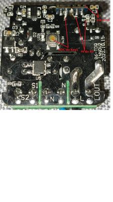
    Photo of the board and description of the connections (at least those paths that I was able to track down)
    ZN268131 WiFi Smart Switch that allows you to connect a bistable button
    It seems to me that the TX, RX, P6, P7 do not have pin pad tracks pulled up.
    ZN268131 WiFi Smart Switch that allows you to connect a bistable button
    I do not write about the power supply because I normally log in to the software.

    Regards
  • #20
    p.kaczmarek2
    Moderator Smart Home
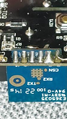
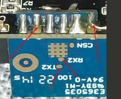
    In general, these TX2 and RX2 could also be used rather. Maybe not TX2 because it's a log output, but RX2 can be controlled from the beginning with software....
    These pads look free?
    ZN268131 WiFi Smart Switch that allows you to connect a bistable button
    That pad on the side is your soldered wire is it?
  • #21
    piratee
    Level 12  
    The one on the right soldered by me 3.3V.
    The plate was terribly folded and I couldn't take it out.
    Even after desoldering and cleaning with tin stripping tape, it was difficult to insert.
    But the transitions from ADC and P8 are because I checked the meter, I just don't know how to handle the software

    Added after 3 [hours] 7 [minutes]:

    And another question.
    By shorting S1 and S2, we turn on the relay, then if I manually break, for example, the ADC pin with P8 or P8 with P26 or P26 with ADC, it will burn the system?
    How to check which pins to short?
  • #22
    p.kaczmarek2
    Moderator Smart Home
    I'm a bit lost in your situation @piratee but there is no need to short circuit the two IOs of the WiFi module. I'm not sure what you want to achieve, but shorting the two IO's won't do it.

    You want to add a button?

    If so, put the button between the mass of WB2S and between one of its IOs and set the role of Btn in the program. Then it will work.

    For "technical" people, I will add that the Btn role turns on the BK7231 programmable pull up resistor, thanks to which you do not need to add anything else in hardware. And debouncing is in the firmware.
  • #23
    piratee
    Level 12  
    Ok, if I assign btn to p8 in the software, will it be ok?
  • #24
    p.kaczmarek2
    Moderator Smart Home
    As long as there is a physical button between the mass and P8, then the "Btn" role on P8 will work for the astable button (the one you press and it returns to its position) and the TglChannelOnToggle role will work for the toggle button (classic, rocker, with two stable positions).
  • #25
    piratee
    Level 12  
    I wanted to assign astable to P8 , P26 or ADC but it doesn't work.
    It may be that I dropped something more during soldering.
    How's Rel doing?
  • #26
    p.kaczmarek2
    Moderator Smart Home
    What does "not working" mean?

    Does the value of the set channel from a given pin change when you press the button?

    The Rel and LED roles (and Rel_n and LED_n, inverted logic) simply put a 1 or 0 state on that pin. If you want to control a relay, you need to have a circuit with a transistor, resistors, a protection diode, and the relay itself. The value issued on the pin is taken from the set channel in the pins, so you can control multiple relays, etc.

    How much is that what you're asking?

    If you want to check if the IO data works, take a 1k resistor, LED diode, connect this diode with a resistor between GND and IO data, of course respecting the polarity, then setting REL (or Led) for this IO and changing the channel value should change the state of the diode (on/off).

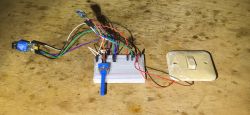
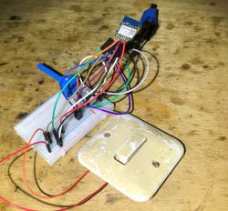
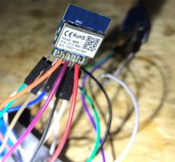
    You must be doing something wrong. Everything works for me the first time. Look here, this is one of my test stands on WB2S donated by a reader, for testing TglChannelOnToggle - toggle switch and everything works:
    ZN268131 WiFi Smart Switch that allows you to connect a bistable button
    ZN268131 WiFi Smart Switch that allows you to connect a bistable button ZN268131 WiFi Smart Switch that allows you to connect a bistable button
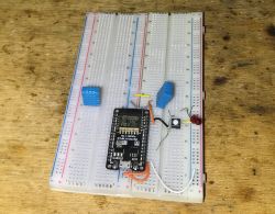
    And here is the BL602/OpenBL602 test stand with astable - it also works (and switches the LED state, I have Btn on channel 0 and Rel on channel 0):
    ZN268131 WiFi Smart Switch that allows you to connect a bistable button
  • #27
    piratee
    Level 12  
    It does not work, i.e. the relay does not pop - it does not turn on the voltage.
  • #28
    p.kaczmarek2
    Moderator Smart Home
    Show pin configuration from OBK.

    Is the pad output 0V or 3.3V (logic zero or one) depending on the channel value?
    (The measurement can only be performed when you power the system from a separate 5V, when powered from the mains DO NOT TOUCH THE SYSTEM).

    Show screenshots.

    Maybe there is no connection between the pad and the transistor (more precisely: its base resistor) controlling the relay? E.g. path intersected?

    Or maybe there was a short to ground somewhere?
  • #29
    piratee
    Level 12  
    Tomorrow I will check what voltage values are on the pins, I have to set and check again.
  • #30
    p.kaczmarek2
    Moderator Smart Home
    Another thing worth noting is that if you power the WiFi module from a separate 3.3V power supply (via LDO), then the relay will not "click".

    The relays are powered by 5V on the board (and sometimes 12V). Simply powering the WiFi module will not power them. This is a common mistake.

    I will say even more - if there are 12V relays on the board, and you connect 5V from USB to the LDO input on the board (AMS1117) and start testing the system, you will also be surprised - the relays do not "click".

    Can you show how you test and power it?