FAQ
TL;DR: ZN268131 Wi-Fi relay (≈22 PLN/~$5) lets you reuse any bistable switch after flashing OpenBeken; “The longer delay of ToggleChannelOnToggle was fixed today” [Elektroda, p.kaczmarek2, post #20381485] Cut one RX trace, program via UART, restore, done.
Why it matters: You keep your existing wall hardware, ditch the cloud, and gain local Home-Assistant control.
Quick Facts
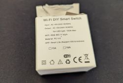
• Supply voltage: 100-240 VAC; relay opens only one conductor [Elektroda, p.kaczmarek2, post #20033093]
• Load rating: 16 A resistive (label on Aubess/Shunshun variants) [Elektroda, anthonythomas, post #20496080]
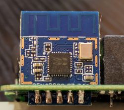
• Module: BK7231T or BK7231N (WB2S/CB2S) with 2 MB flash [Elektroda, p.kaczmarek2, post #20033093]
• Price: 20–30 PLN including shipping [Elektroda, p.kaczmarek2, post #20033093]
• Flashing lines needed: 3.3 V, GND, RX, TX—no GPIOs [Elektroda, p.kaczmarek2, post #20033093]
1. What makes ZN268131 different from typical Sonoff-style relays?
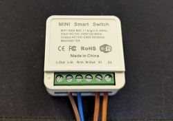
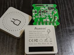
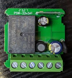
It provides two screw terminals (S1, S2) for an external bistable switch, so every throw flips the relay, regardless of lever position. Classic Sonoff units expose only a momentary button on the case [Elektroda, p.kaczmarek2, post #20033093]
2. How do I wire a bistable rocker or wall toggle?
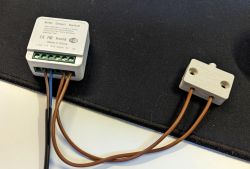
Bridge the rocker between S1 and S2 (on ZN268131) or between any free GPIO and GND on other OpenBeken-flashed boards. In firmware set that pin role to “ToggleChannelOnToggle” so each change toggles the relay [Elektroda, p.kaczmarek2, post #20033093]
3. What are the safe three steps to flash OpenBeken?
- Power the board from a separate 5 V supply before the AMS1117 regulator—never from mains.
- Connect 3.3 V, GND, RX, TX to a 3.3 V USB-UART adapter.
- Start bkWriter, then briefly cycle 5 V to enter bootloader; program binary, reconnect the cut trace [Elektroda, p.kaczmarek2, post #20033093]
4. Why must I cut the RX trace on some units?
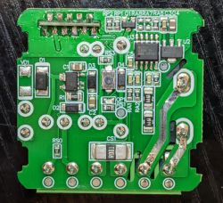
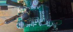
The RX pin is also tied to an onboard push-button with a strong pull-up; it holds the line high and blocks the bootloader. Isolating the trace lets the UART drive RX during flashing, then you bridge it back afterwards [Elektroda, p.kaczmarek2, post #20033093]
5. Which OpenBeken pin roles work out of the box?
Factory template: Rel → P8, LED_n → P7, Btn → P10, ToggleChannelOnToggle → P26 on many Aubess/Shunshun units [Elektroda, anthonythomas, post #20496080] Verify with a meter because other batches use P11 or P14 instead [Elektroda, kicius, post #21363483]
6. I see 3.8 V on the 5 V rail and the module won’t boot—what failed?
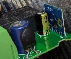
A dried-out filter capacitor causes the capacitive dropper to sag; Tuya’s low-power mode masked it, but OpenBeken pulls more current, exposing the fault [Elektroda, kptzbik1, #20112145; p.kaczmarek2, #20112270]. Replace the 470 µF/10 V cap with a low-ESR part rated for SMPS duty.
7. The toggle switch reacts about 1 s late—fix?
Upgrade to OpenBeken build ≥ 2023-01-12; the debounce logic was rewritten and the delay removed [Elektroda, zifban19, post #20381485] “The longer delay … was fixed today,” the maintainer confirmed [Elektroda, p.kaczmarek2, post #20381485]
8. Can I retrofit other smart relays to accept bistable buttons?
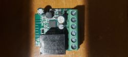
Yes. Any Tuya-based relay with spare GPIOs can run OpenBeken; assign one free pin as ToggleChannelOnToggle and wire it to a switch. The guide shows a Sonoff-style board with WB2S where only two jumper wires were needed [Elektroda, p.kaczmarek2, post #20033093]
9. How do I add an automatic 15-minute shut-off?
Create a LittleFS script:
AddEventHandler OnClick 0 setChannel 1 1
addTimer 90000 setChannel 1 0
This turns channel 1 on at the click and off after 900 s (15 min) [OpenBeken Docs].
10. Must L and N be connected in the marked order?
The relay functions if you swap them, but doing so can leave the lamp socket live when “off,” increasing shock risk. Always follow the L→L1, N→N1 labels and isolate power before servicing [Elektroda, p.kaczmarek2, post #20557122]
11. What hardware failures appear in cheap mini switches?
Low-grade 470 µF electrolytics often bulge within a year, dropping the 5 V rail and killing Wi-Fi and relay drive [Elektroda, Szyszkownik Kilkujadek, post #21364784] Replace with quality low-ESR parts and enable PowerSave 1 to cut stress [Elektroda, p.kaczmarek2, post #20354661]
12. How is 433 MHz RF added without extra code?
Many three-way RF versions piggy-back the touch button line: the RF chip briefly drives the same GPIO when a matched code arrives, so OpenBeken sees it as a normal button event—no firmware change needed [Elektroda, p.kaczmarek2, post #20195490]

 -.
-.
