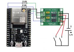
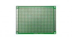
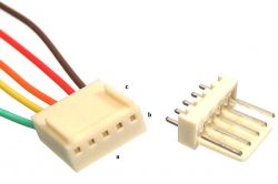
I need to drive an external signal to two inputs on the ESP32 (specifically, I assumed the use of GPIO23 and GPIO22), and as these are two floats drowned in tanks of water, I found that I would use galvanic separation using a two-channel module with PC817 optoisolators. Generally on the 'short' it seemingly works. For testing purposes, I apply voltage (3.7V) from the 18650 battery to the input of the optoisolator module (the target is to have 5V through these floats - they act as a jumper depending on the position) and the output connected directly to the GPIO on the ESP32 and of course to ESP ground. Generally works.... until I put it together on a prototype board, wired, added connectors etc.... Then it turned out that one GPIO works correctly (we power up the optocoupler - the state changes) oh the other one triggers both.... That is, applying power to the second optocoupler causes both GPIOs to change state.... The same happens without the optocoupler if I short-circuit the GPIO directly to ground (briefly if I short-circuit only the pins on the ESP itself this does not happen). I added 10k pull-up resistors between GPIO and 3.3V and GPIOs shorted to ground work fine, the state only changes when the GPIO data is shorted to ground. The problem is that they have stopped responding if we feed a signal through the optocoupler. Applying power to the optocoupler input changes absolutely nothing about the state of the GPIO input. What have I done wrong?
Tailor
Tailor


