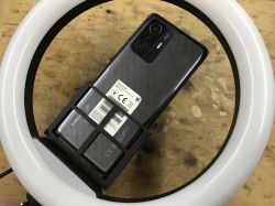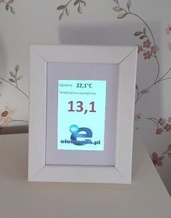
At the beginning, an explanation to the title - it is not a typical thermometer, because it does not measure anything, but simply displays the temperature taken by other sensors. However, I found the "temperature display" to sound strange. But "to the bedroom" has its justification, which I will write about later.
Some history
Indications of the outside temperature in the bedroom make sense - after all, it is there that we decide how to dress. Initially, the temperature was displayed by an old Lenovo tablet - thanks to the Chrome browser and the ability to display it in full screen, it looked pretty decent. The problem was the brightness of the light - at night the bedroom is supposed to be dark. The browser does not have the ability to control the backlight. I partially solved the problem by overlaying a semi-transparent "div" based on astronomical clock data. It even worked quite well, but the Wi-Fi or power icons shone brightly anyway. However, it was enough to turn the screen so that it could not be seen from the position of the pillow and it was OK. One time, however, I noticed that the display bulged, and after a while, as the bulge increased, the display began to malfunction. I've read about batteries swelling on constant power, but I thought it wouldn't affect Lenovo. The problem arose - to get a new tablet or to do it "your way". Once, thinking about my own temperature display, I bought a TFT module 480x320px. Basically, I wanted a large display, not a high resolution, but then I couldn't find anything more interesting than this 4 "display. So I decided to build my own structure based on ESP8266.
Frame construction
The basic problem when building a device "in sight" is of course the casing. I decided to make the whole thing in the form of a picture frame. There are also other frames with real photos on the chest of drawers, where the "thermometer" is located - I thought that everything would fit nicely:
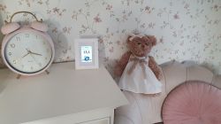
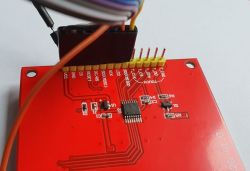
It was my first project with a TFT display - that's why I did some tests first:
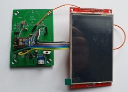
I usually build circuits on a universal board, but I had a ready board for ESP-12 for a completely different project (known problem - you have to order a few pieces) - I decided to do "recycling". I will not draw a diagram, because the appropriate ESP pins (SPI interface) are simply connected to the display. Additional pins are:
Code: C / C++
and GPIO15 to control the TFT backlight. The choice of GPIO15 was not accidental. During startup, this pin is forced low (ESP8266 requires it). As a result, the screen is not backlit for the entire duration of the ESP start, and only when everything is ready, the backlight is turned on.
As I mentioned, dimming was important, so the frame was equipped with a photoresistor:
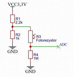
The only ADC input of the ESP8266 processor came in handy. The high resistance of R4 may be surprising. It results from the fact that the system was supposed to have good resolution at very low illumination.
Construction
After buying the frame and tearing off the back foot, I cut a hole for the display:
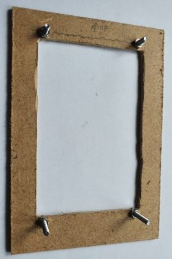
The precision of the cut is not particularly important - there will be a passe partout in the front that will mask everything. However, it is important to place the hole vertically - the active part of the display is not in its center, which should be taken into account when cutting the hole.
After mounting the display on the front, it looks like this:
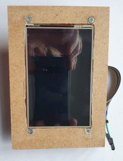
The screws are conical and have their sockets so that there is one even plane at the front. Because the plate is thin, I added a little drop of glue under the screw heads to strengthen the whole thing. Side view:
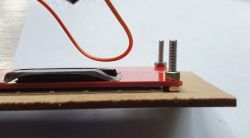
The thickness of the plate and nut matched the thickness of the display perfectly.
And this is what it looks like after assembly:
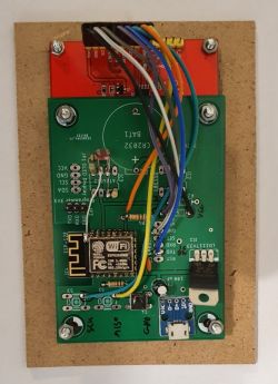
The top screws from the board are not attached to the display - they only act as spacers.
Rear view of the finished frame:
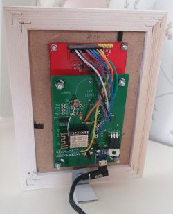
Because I do not use the touch panel, I left the original plexiglass in the frame.
Software
ESP programming I did as usual in Arduino. To support the display, I decided to use the TFT_eSPI library, which works very well with my display. The authors of the library solved the problem of configuring the control pins and the type of display in an interesting way - everything is in the "User_Setup.h" file. This solution has the advantage that after a one-time configuration, you can build sample projects that work right away! The "first fire" was the example of displaying a JPG image - it worked very well, and I found out that I have a well-connected and functional display. The next step is to display subtitles - examples are also available here. I decided to modify them a bit and check what about Polish characters. Unfortunately, they weren't. Later I read that it can be done, but it's not easy. This cooled my enthusiasm a bit, especially since I wanted to use nice, big characters.
I decided to solve the problem differently - I decided that the frame would only display the entire image, which would be created on the server side using PHP and the GD library. The GD library gives me access to writing using TrueType, and since PHP is an interpreted language, it's very easy to modify - I don't have to compile, upload, etc.
The problem remained how to upload an image from PHP to ESP. I rejected JPEG compression - it's a lossy compression, and I didn't want to have a blurry image at the edges. The PNG compression module did not work (probably requires more RAM). I was still thinking about GIF, but in the end I decided on my own solution with my own compression.
I decided that PHP will immediately prepare the image for display, i.e. it will encode it to 65k colors (RGB 565), which is required by the TFT display. Initially, the data was sent uncompressed - each row consisted of 320 pixels or 640 bytes. The entire image was thus 307,200 bytes in size. It worked very nicely and interestingly, but slowly. I found the wifi on the ESP8266 to be very slow. The redraw took over 2 seconds. Because they can be done without erasing the previous content, an interesting "blind" transition effect was created, which can be useful when someone wants to make an electronic photo frame.
However, I wanted speed, so I added RLE-based compression. Below is a description of the method used.
Compression
Since one pixel is 2 bytes, I decided to encode everything on two bytes - in the further description I will call it a "word", which can contain numbers or an RGB color (in the 565 system). The basic assumption was easy reading on the ESP side. Therefore, the first word contains the number of words in the line. The next word is the control word (let's call it n) - if it is less than 10000, it means that the next n words should be rewritten as pixels. If n is greater than 10000, then the next word (pixel) should be repeated (n-10000) times. We use such encoding to the end of the line - that is, the next control word and data, etc. After encoding the line, the PHP code checks whether the encoded string (row of pixels) is not longer than uncompressed. In this case, compression is canceled for that row, and ESP, when it reads that the row is 320 words long, knows that it is not compressed. For the picture below:
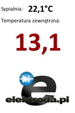
Compression yields a resulting size of 43,160 bytes, which is 14% of the original. I considered it a very decent result.
Arduino code
[syntax=c]// Flash 4MB esp8266
#include
#include
#include
#include
#include
#include
#include
// WiFi
const char* APname = "TERMOMETR";
const char* APpassword = "moje_haslo";
const char* host = "192.168.0.24";
const char* privateKey = "termometr1";
#define LED 2 //wewnętrzny LED
#define BACK 15 //podświetlanie ekranu
#define WERSJA "1" // która wersja
#define WIDTH 320
#define HEIGHT 480
#define WIDTH2 (2*(WIDTH))
TFT_eSPI tft = TFT_eSPI();
void setup() {
pinMode(BACK, OUTPUT);
digitalWrite(BACK,LOW);
analogWriteRange(10000);
analogWriteFreq(40);
pinMode(LED, OUTPUT);
digitalWrite(LED,LOW); //sygnalizacja startu
delay(2000);
digitalWrite(LED,HIGH);
delay(300);
WiFiManager wifiManager;
wifiManager.setDebugOutput(false);//wyłączenie debuga
wifiManager.setConfigPortalTimeout(180);
if(!wifiManager.autoConnect(APname,APpassword)) {
ESP.reset();
delay(5000);
}
digitalWrite(LED,LOW); //połączono 2 błyski
delay(300);
digitalWrite(LED,HIGH);
delay(300);
digitalWrite(LED,LOW);
delay(300);
digitalWrite(LED,HIGH);
ESPhttpUpdate.update(host, 80, "/www/OTA.php", String(APname)+":"+WERSJA+":"+WiFi.localIP().toString());
tft.begin();
tft.setRotation(2);
tft.fillScreen(TFT_NAVY);
}
WiFiClient client;
int back=10000;
int licznik=0; //30*2s=1min
int analog=1024;
int popanalog;
void loop() {
delay(2000);
popanalog=analog;
analog=analogRead(A0);
if (abs(analog-popanalog)>100)
licznik=0;
if (licznik>0){
licznik--;
return;
}
const int httpPort = 80;
if (!client.connect(host, httpPort)) {
licznik=10;
return;
}
String url = "/lcd/term.php";
url += "?private_key=";
url += privateKey;
url +="&foto="+String(analog);
client.print(String("GET ") + url + " HTTP/1.0\r\n" +
"Host: " + host + "\r\n" +
"Connection: close\r\n\r\n");
unsigned long timeout = millis();
while (client.available() == 0) {
if (millis() - timeout > 15000) {
client.stop();
return;
}
delay(1);
}
client.setTimeout(15000);
String odp;
String comm="";
String s;
while (true) {
odp=client.readStringUntil('\n');
odp.trim();
if (odp=="")
break;
if (odp.indexOf("X-Command:")==0){
comm=odp.substring(10);
comm.trim();
}
if (odp.indexOf("X-PWM:")==0){
s=odp.substring(6);
s.trim();
back=s.toInt();
}
}
if (comm=="Restart"){
ESP.reset();
delay(5000);
}
if (comm!="IMG"){
client.stop();
licznik=10;
return;
}
analogWrite(BACK,back);
licznik=30;
//odczyt obrazu
uint8_t buf[WIDTH2];
uint8_t buf2[WIDTH2];
uint16_t ile;
tft.startWrite();
for (int i = 0; i < HEIGHT; i++) {
yield();
timeout = millis();
while (client.available() 1000) {
tft.endWrite();
client.stop();
return;
}
yield();
}
ile=client.read()*256+client.read();
int len = client.readBytes(buf,ile * 2);
tft.setAddrWindow(0, i, WIDTH, 1);
if (ile==WIDTH)
tft.pushPixels(buf, WIDTH);
else {
int w=0;
int d=0;
while (d
Cool? Ranking DIY


