FAQ
TL;DR: 10 confirmed cases of the JBL Bar 3.1 / SW10 SMPS failing at R534-R535 & SMK1265 MOSFETs; “Replace the IC, the MOSFET and the shunts” [Elektroda, azaghorth, post #20370600] Use 0R24 Ω shunts and a 34 V DC, ≥60 W external supply when repair is uneconomic. Total parts cost: ~€15; service fee quoted: €75.
Why it matters: Knowing the right resistor value and voltage prevents repeat blow-ups and saves money.
Quick Facts
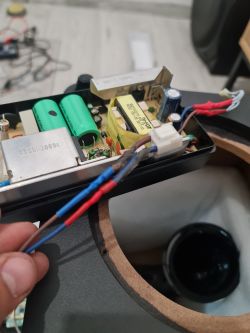
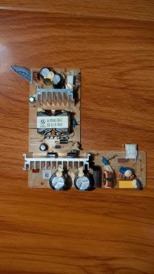
• Original SMPS: 34 V DC, 150 W, 3 × V+, 3 × GND, 1 × 12 V STBY [Elektroda, awcon, post #20358386]
• Shunts R534/R535: 0.24 Ω, 1 %, 2512 code “0R24” [Elektroda, oldking, #20333378; psooya, #20345529]
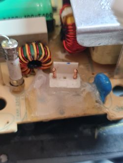
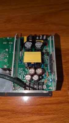
• Failure chain: SMK1265 pair + NCP1271 driver damaged on every inspected board [Elektroda, SteCal, post #20330310]
• DIY parts: PLN 70–90 (≈€15–20) vs. PLN 350 service fee [Elektroda, oldking, post #20373641]
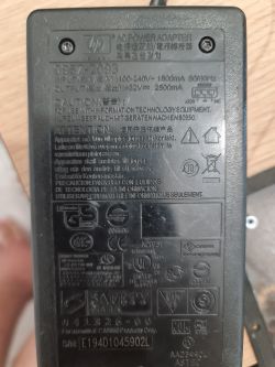
• Drop-in PSU: HP 0957-2260 32 V 5.625 A (180 W), no standby line [Elektroda, oldking, post #20406587]
What usually kills the JBL Bar 3.1 / SW10 power board?
A bulged CE512 electrolytic raises ESR, the SMK1265 MOSFETs short, current spikes, and the 0.24 Ω shunts vaporise before protection acts [Elektroda, SteCal, #20330310; azaghorth, #20370600]. Over-voltage events (>253 V mains) accelerate the chain [Elektroda, Beretti, post #20549958]
What are the correct values for resistors R534 and R535?
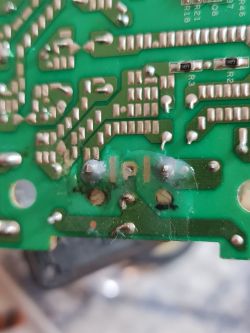
Both are 0.24 Ω (code R240/0R24), 1 % metal-strip shunts in 2512 packages [Elektroda, oldking, #20333378; psooya, #20345529]. Using higher values starves the driver; lower values overstress the MOSFETs.
Which parts must be replaced after the typical failure?
Replace: 1. SMK1265 MOSFET pair. 2. NCP1271 (IC1271) PWM controller. 3. R534 and R535 shunts. 4. Bulged CE512 capacitor. 5. R561 0 Ω link if open [Elektroda, SteCal, post #20330310] "Check every semiconductor before power-up" [Elektroda, ElDesign, post #20326476]
Is a schematic available for the 40-N150SE board?
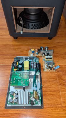
The SW10 service manual contains an identical 40-N150SE diagram, covering all resistor codes and test points [Elektroda, VinBaxter, post #20429133]
What DC output does the original SMPS deliver?
The PCB silk shows 34 V DC with a separate 12 V standby pin [Elektroda, awcon, post #20357299] 50 V electrolytics give 30 % headroom.
Can I swap in an external power supply instead of repairing?
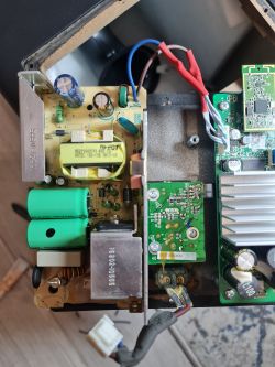
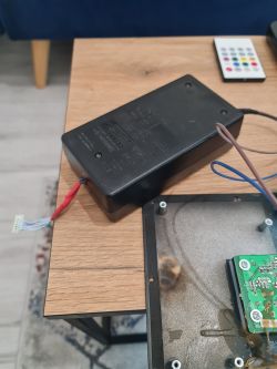
Yes. Users run HP 0957-2260 (32 V 5.6 A) or 36 V adjustable bricks dialled to 34 V. Units ≥60 W work; 180 W gives margin [Elektroda, oldking, #20406587; E-Service, #20684528].
How do I wire the external PSU?
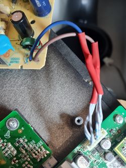
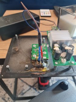
- Twist the three +34 V wires together and solder to PSU +. 2. Twist the three GND wires and solder to PSU –. 3. Leave the single STBY wire floating. Confirm polarity before power-up [Elektroda, oldking, post #20413416]
What happens if I use only a 30 W adapter?
Under high bass loads the adapter current-limits, voltage collapses, and distortion rises. It may overheat or fail, possibly sending spikes that kill the amplifier stage [Elektroda, aaanteka, post #20744226]
Is 36 V safe for the amplifier?
36.6 V exceeds design by 2.6 V. "It may be too much; lower to 34 V" [Elektroda, oldking, post #20637960] Adjustable supplies should be trimmed to ≤34 V to avoid thermal stress.
Why does standby stop working after the swap?
External bricks lack the 12 V logic line. Without it, the amp remains fully on and must be unplugged to power-down [Elektroda, oldking, post #20431052]
Is professional repair cost-effective?
Service centres quote PLN 350 (~€75). DIY parts cost about €15, but require SMD soldering. Buying a new 180 W brick costs €20–30 [Elektroda, oldking, post #20373641]
Are there safety concerns when mounting a new PSU inside the cabinet?
Yes. Uncertified bricks may overheat from Class-D switching noise and alter the acoustic volume. A colleague calls it “a veritable lottery” [Elektroda, aaanteka, post #20684596] Ensure UL/CE ratings and leave ventilation.
Does the SW10 amplifier board fit the Bar 3.1 sub?
Yes, both use board 40-SB210U-AMD2G. Failures on that board can also mimic pairing issues [Elektroda, VinBaxter, post #20705843]
How can I verify no further shorts before re-powering?
Measure resistance from +34 V to GND; it should exceed 1 kΩ. Check MOSFET drains to source for open circuit. Verify NCP1271 outputs are not shorted to GND [Elektroda, azaghorth, post #20370600]
Edge case: sub powers up randomly or not at all—PSU or control?
Intermittent power is usually the auto-on logic, not the 34 V rail [Elektroda, aaanteka, post #20550025] Check the control PCB and RF module before replacing the SMPS.


