Hi,
I have designed a PCB with the Wemos D1 Mini. In brief: the ESP controls five MOSFET transistors and one optotriac (MOC3021). The whole thing is powered by the HLK-5M03. I will mention that I tested all the modules (triac control, mosfet control) before transferring the concept to the schematic and to the PCB. After soldering the board I had problems with getting the circuit to work
The problem was that the ESP would not start. I suspected via the UART that it was spitting out a string of "bushes" after a reset and would not go to network connection. This was happening when the D1 Mini was embedded in the PCB. After removing it from the PCB and connecting the ESP via the cable to the PC, the D1 would boot normally (connect to the network and execute the program).
Connecting the D1 module via cable to the PC (while embedding D1 in the PCB) and powering it via USB (with HLK-5M03 disconnected) had the same effect as above - ESP on startup spit out a few bushes and stopped, without proceeding to the WiFi network connection procedure.
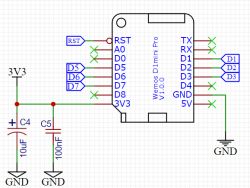
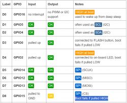
In D1 Mini I use such pins as: D1, D2, D3, D5, D6, D7.
I started to wonder if by chance the loads (mosfets, to which I didn't connect anything during the first tests) don't cause problems with ESP starting. So I connected the ESP on the PCB "in the air", connecting only 3.3 V and GND. It turned out that the circuit works.
For the moment I am able to start the circuit like this:
1) I start the designed board without the D1 Mini.
2) I insert the D1 Mini into the socket on the board starting from the back pins, so that I first connect 3.3 V to 3.3 V and GND to GND.
3) I wait a second, D1 Mini connects, I insert it all the way into the socket and the whole circuit from the PCB works as it should, i.e. as intended.
The conclusion then is that I have a problem with the ESP starting while its leads (D1, D2, D3, D5, D6, D7) are connected to the mosfets and the optotriac at the start. However, once the ESP passes the startup, it then works properly in the PCB.
What can I do about this fiasco? How can I solve this problem and make the ESP start without "combinations"? I am able to do something software or hardware without much interference? The only thing I can think of is a power sequencer: when the voltage is applied, the ESP starts first, and only then the other circuits (i.e. ground to the mosfets and optotriac, for example). Only it's too late for that at this stage - the board is ready.
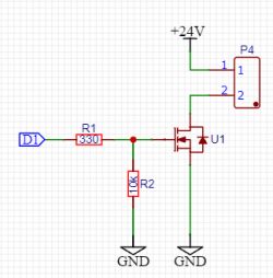
I have included the schematic elements below: D1 Mini, mosfet control (5 pieces), optotriac control.
Please give me any hints, tips, explanations as to why the ESP behaves this way, and any suggestions on how to solve the problem. Thanks in advance.


