Hello
Colleagues! I made such a controller (controls 4x LED strings on 230V). Controller with option: WiFi + IR - so for convenience.
Some time ago a prototype was created on a universal board. And once I got to grips with the software, I decided to design the PCB. I ordered the boards from jlcpcb.com.
When the boards arrived I assembled 1x copy and flopped. A whole Sunday wasted looking for a bug. Unfortunately I failed.
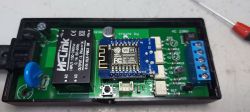
Well, the problem is very strange. Assembled circuit:
 .
.
It does not want to start when resistors R3 and R4 are soldered in
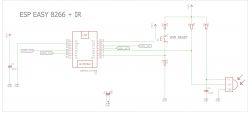
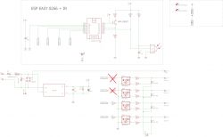
here is the schematic:
 .
.
At first I thought it was some error in the PCB design: a short circuit, missing ground, or a faulty component. So I checked the PCB for possible short circuits, replaced the thyristors, MOC3041 optotriacs and no improvement.
I figured I would connect the Arduino serial monitor and eavesdrop on the transmission. Unfortunately no connection could be made.
 .
.
When I pull the ESP8266 out of the cradle, the module itself starts up and then draws 78mA (which is about the same as the working prototype) and works fine (connects to WiFi).
But when I put the ESP8266 module back in the cradle and apply power, the chip draws about 46mA
I conclude that it crashes on startup.
I don't know what is!
I have checked the power supply.
The problem goes away when I unsolder R3(D3) and R4 (D4)
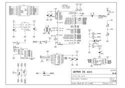
The difference between the prototype is that in the prototype there were 4x Leds in place of the optotriacs and the power was taken from the USB of the computer. I also noticed that in the prototype the Leds at the output of D3 and D4 always flash briefly on start-up
Colleagues! I made such a controller (controls 4x LED strings on 230V). Controller with option: WiFi + IR - so for convenience.
Some time ago a prototype was created on a universal board. And once I got to grips with the software, I decided to design the PCB. I ordered the boards from jlcpcb.com.
When the boards arrived I assembled 1x copy and flopped. A whole Sunday wasted looking for a bug. Unfortunately I failed.
Well, the problem is very strange. Assembled circuit:
 .
.
It does not want to start when resistors R3 and R4 are soldered in
here is the schematic:
 .
.
At first I thought it was some error in the PCB design: a short circuit, missing ground, or a faulty component. So I checked the PCB for possible short circuits, replaced the thyristors, MOC3041 optotriacs and no improvement.
I figured I would connect the Arduino serial monitor and eavesdrop on the transmission. Unfortunately no connection could be made.
 .
.
When I pull the ESP8266 out of the cradle, the module itself starts up and then draws 78mA (which is about the same as the working prototype) and works fine (connects to WiFi).
But when I put the ESP8266 module back in the cradle and apply power, the chip draws about 46mA
I conclude that it crashes on startup.
I don't know what is!
I have checked the power supply.
The problem goes away when I unsolder R3(D3) and R4 (D4)
The difference between the prototype is that in the prototype there were 4x Leds in place of the optotriacs and the power was taken from the USB of the computer. I also noticed that in the prototype the Leds at the output of D3 and D4 always flash briefly on start-up


