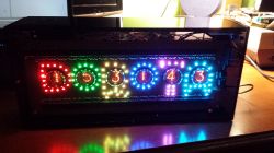
A special person deserved an equally special gift, and since I`m not a fan of buying surprises, I decided to "make" something with my own hands.
1. Introduction, motivation
2. Outline of the structure
3. Board with diodes - design (connecting diodes)
4. Board with diodes - design (latches)
5. Eagle - commands
6. Board with diodes - execution
7. Tile with lamps - design
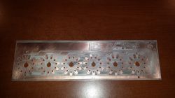
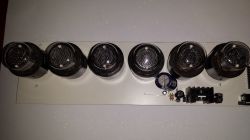
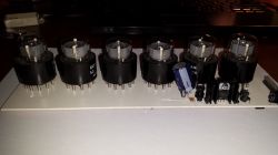
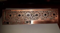
8. Plate with lamps - execution
9. Buttons
10. Nixie boost converter.
11. Housing
12. Software
13. Final result
1. Introduction, motivation
A special person deserved an equally special gift, and since I`m not a fan of buying surprises, I decided to "make" something with my own hands.
Sometimes it`s hard to find someone`s taste, especially if we don`t know much about them, so I chose something universal and practical: a clock with Nixie tubes (after all, everyone likes to know what time it is).
However, to emphasize the `uniqueness` of the surprise and to make the recipient feel even more that it was something especially for her, I decided to personalize the gift in some way and put her name in it.
Since DOROTA has 6 letters and most of them have bellies inside, I came up with the idea that each letter would contain one number - a nixie lamp. The letters of the name will be illuminated with LED diodes, which will additionally add visual variety to the somewhat austere appearance of this type of clocks and give it a certain modernity.

//idea.png
As LEDs, I decided to choose miniature RGB LEDs in SMD 1206 RGB housing. I wanted to be able to control each of the R/G/B components of each diode separately, which would open the door to many different interesting effects.
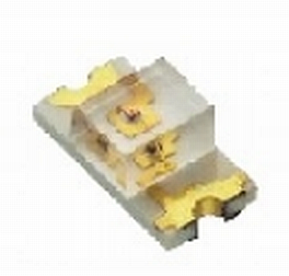
//led.png
Initially, I had the idea to place 16 diodes per letter (16 * 6 = 96), but then I came to the conclusion that some of the letters were more complicated, others less, so in the end I stayed with 96 pieces in total, but the division was as follows:
* (D) - 16 diodes
* (O) - 14 diodes
* (R) - 20 diodes
* (O) - 14 diodes
* (T) - 12 diodes
* (A) - 20 diodes
2. Outline of the structure
For the construction, I decided to use domestically produced DOLAM LC513 or LC516 lamps (I wasn`t decided yet).

//lc513_516.png
Most clocks of this type are built on a single printed circuit board, but in this case, due to the relatively high height of the nixie lamps (several cm), the diodes should be placed flush with the very tip of the lamp, which forced the creation of two printed circuit boards - the first one with diodes. (and holes cut out), and the second one with lamps.
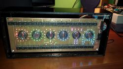
//20231229_153127.jpg
3. Board with diodes - design (connecting diodes)
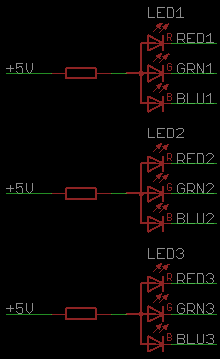
Most (all?) RGB LEDs have either all anodes or all cathodes connected and there are 4 pins available on the outside. My diodes have a common anode. Controlling many such diodes can be done in several ways:
(1) The anodes of all diodes to +5V, a separate resistor in series with each cathode
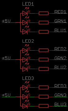
//led_con1.png
+ Possibility to control each of the components separately
- Need to solder resistors 3 times the number of LEDs
(2) A single resistor in series with the anode
+ Fewer resistors
- Only one of the components (R/G/B) of each diode can be lit at a time, because exposing a low level to each of them at once will cause only the diode with the lowest voltage drop (red) to light up. To be able to control all colors, you need to multiplex (1/3 of the time we turn on the R components, 1/3 of the time G and 1/3 of the time B)
- Single resistor = different current for each component
//led_con2.png
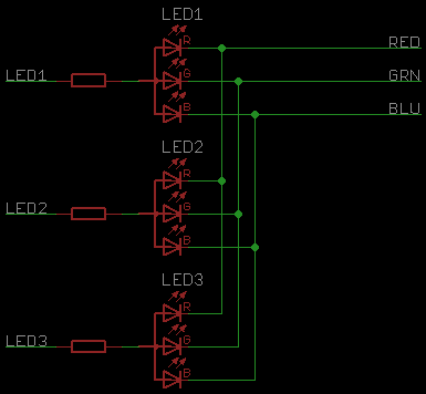
(3) Since only one of the components is lit at a time, a modification of the above method is to control each anode separately and connect all cathodes of the same color together and pull only the one that is to be lit to ground.
//led_con3.png
+/- Advantages and disadvantages as above
+ Saves the number of pins
- previously, only the +5V line had to go around each diode, which could be successfully implemented on one layer without vias (blue line = +5V)

//vcc.png
and now they must be three lines (R, G, B), which requires the use of 2 layers and 2 or even 3 vias per diode.
4. Board with diodes - design (latches)
In addition to all this, there is also the choice of how to expand the number of I/O pins of the microcontroller - with 96 diodes, 96 * 3 = 288 pins are needed. For example, shift registers (74595) or regular octal registers (74574) can be used.
Registers 74595 seem to be a good idea at first glance (small number of microcontroller I/O pins involved):
* single serial data input signal
* common serial shift clock signal for all registers,
* possibly also a separate common serial latching clock signal,
* possibly also a common zeroing signal
However, the 14-pin housing of these registers has a certain drawback - the QB, QC, QD, QE, QF, QG, QH outputs are located on one side of the housing, and the QA output is on the other - this complicates the routing of the paths, because now the entire signal bundle (GND, VCC) , CLK, RST, OE) must properly go around all the chips, and the QA pin on the other side will get in the way, which will force part of the track to go to the second layer - two additional vias for each chip.
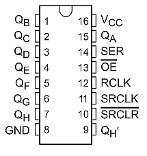
//74595.png
That`s why I preferred 74574 chips: 96 diodes * 3 components / 8 outputs per chip = 36 chips
Here, each system requires a separate clock line (36 clocks) and a common 8-bit data bus (36 + 8 = 44 pins)

//74574_1.png
However, I connected them in such a way that each upper and lower chip has a common clock, while all the upper chips have their own and the lower ones have their data bus (18 + 8 + 8 = 34 pins)
Both buses are not controlled directly from the microcontroller, but an additional 37 buffer latches data from one bus to the other, which reduced the number of pins to: 18 + 8 + 1 clock for the switch = 27)

//74574_2.png
Additionally, as you can see, the inputs of one latch are arranged as D1..D8 and the next one as D8..D1, thanks to which the "serpentine" of paths can be shorter:
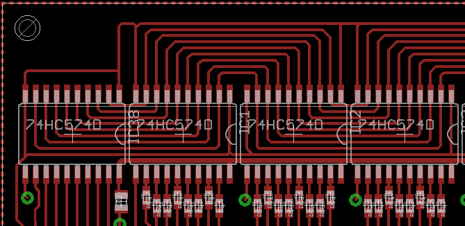
//paths1.png
5. Eagle - commands
Here, as a small interlude, I will insert something very useful in Eagle.
Few users probably know (or use) the so-called command - e.g. by typing
MOVE IC1 (1.0mm 1.0mm)
we move the element called IC1 to the position with coordinates X=1.0 mm y=1.0 mm, thanks to which we save clicking.
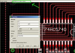
//commands.PNG
But even fewer people probably know that Eagle allows you to perform the so-called scripts (ULP files).
Such a file is nothing more than a program in a language very similar to C, which allows you to execute these commands.
And, for example, if we want to place 18 IC1 ... IC18 systems next to each other so that they lie on the coordinates
(-16 36), (-2.5 36), ...
then just call the program like this:
string cmd = "";
for (i = 1; i <= 18; ++i) {
	real x = -16 + 13.5 * (i - 1);
	real y = 36
	angle = 180;

	sprintf(cmd, "%sMOVE IC%d (%1f %1f);\r\n", cmd, i, x, y);
	sprintf(cmd, "%sROTATE =R%f IC%d;\r\n", cmd, angle, i);
}


exit(cmd);
I`m saying this because manually placing diodes on the arcs that form the letters would look crooked, but it`s elegant.
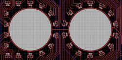
//script1.png
These scripts also make it very easy to create cases for your own components. In 2 minutes I created a housing for a nixie lamp, which has 11 pins evenly distributed around a circle and, additionally, by rotating them by such an angle that, by changing the type of "pad" from round to "offset", they were arranged concentrically.
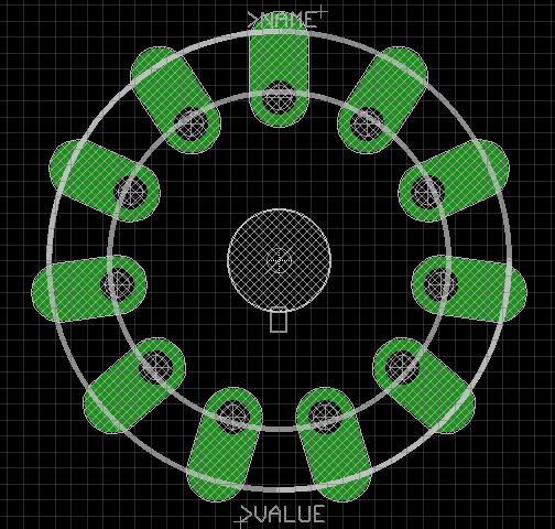
//script 2.png
A serious limitation was the need to fit the board onto an A4 sheet of paper. The margin of reserve was about a centimeter. And you have to be careful, because the eagle does not warn you if the tile does not fit on the paper, it will "silently" reduce the printout to fit.
As for how to connect the diodes - I wasn`t entirely sure, so I gave myself the option of placing a resistor both at the anode and at each of the cathodes (if I decide on one of them, I will simply connect the second resistors with tin).
After a dozen or so hours spent on Eagle, I had a ready version of the board.
The whole thing, which I didn`t mention, is powered by an Atmega 64 microcontroller. The board also has a real-time clock with a battery that maintains the date, a USB socket in the board if I wanted to use it somehow, a pin strip for connecting the control buttons and a 20-pin connector for connecting the board with nixie lamps (10 digit segments + 6 lamps + 2*GND + 2*5V)


//pcb1-top.png, pcb1-bottom.png
The board turned out really elegant, practically everything was placed on the upper layer, on the lower layer there are only clock lines going to the latches and a microcontroller with peripherals.
6. Board with diodes - execution
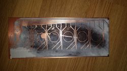
It was finally time to make the board (thermal transfer). I didn`t know for sure whether I was going crazy with the sun, because I had never digested such a large slab in my life. And there were many obstacles
1) merging two layers of such a large plate is extremely difficult - even if you manage to fit all the corners, something inside will always be a millimeter apart because the paper in the printer has waved. Therefore, when ripping, the area with the microcontroller was the most important (there is a high density of vias there).
2) Pressing such a large tile with a laminator takes a lot of time - copper loses heat quickly and needs to be passed through the laminator several times.
3) Soaking the paper - unfortunately, for the first time, the plate did not fit into the plastic container with water, powder and dishwashing liquid and I had to move to... the sink, having previously clogged the drain with a cork
4) The millimeter-sized tile fits in my etching machine, but with such dimensions it is impossible to ensure that the whole thing etches evenly, unless we have a beautifully aerated etching machine.
The first time I failed on the second point - I don`t know if I didn`t sand the laminate with sandpaper or if it wasn`t warm enough, but the toner didn`t stick to one of the corners. Discouraged by this pace of work, I had to take a break for 2 weeks...
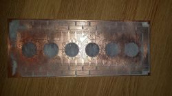
//20231220_094921.jpg 20231220_094928.jpg
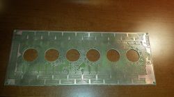
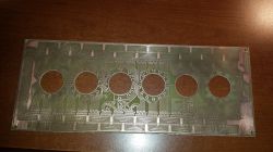
After 2 weeks I came back, made a second attempt and... I got the most beautiful plate in my life. I was terribly worried about the etching, because it took over an hour, I took the plate out several times and put it into the etching machine, rotated, to "average" the effect of etching on different areas. It turned out great because the copper layer was thick (no etching), the etching mixture was weak and the toner layer was thick.
I had the most "fun" with milling the holes for the nixie tubes - because there was a power path around them and I felt a bit like a surgeon.
//20231220_182126.jpg 20231220_182136.jpg
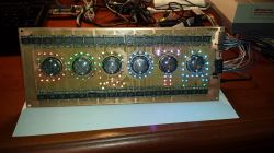
Then it was time for soldering - 96 diodes, 96 resistors and... 288 mini-tin jumpers placed so close to each other that at times I had the impression that I was doing miracles with a soldering iron. I soldered the diodes to the first letter (A) for about 1.5 hours, then I gained practice and it took me about 30 minutes per letter. I was actually afraid whether I would be able to solder the diodes manually with such a small pitch, but it turned out great. I had to unsolder several diodes with hot air and solder them again, but each of them survived - I think they are extremely resistant.
//20231222_120605.jpg
7. Tile with lamps - design
With the first board ready, now it`s time for the lamps. However, I decided to use LC-516 because I had more of them. They are larger, but with the size of the clock they will probably fit in even better. 6 nixie tubes, multiplexed on transistors.
In addition, a 180V voltage converter based on Atmega8. Previously, this type of converters increased my voltage from 5V because I powered them directly from USB. However, here the whole thing will be powered by a 9V power supply, so I gave myself the opportunity to choose whether it would be better to supply 5V or 9V to the converters (selected with a jumper).
There is also a power supply block for diodes and microcontroller: 9V->5V. Here, I was also not sure whether it would be better to use a regular 7805 + heat sink, or maybe with so many diodes there would be less losses if I use a step-down converter (LM2596). I also gave a choice of how to obtain 5V with a jumper.
After a few hours, the board was also very polished - all in one layer and only one grommet (!)

//pcb2-top.png
Here again the "tricks" in Eagle came in handy - as you can see, many fragments of the paths connecting the segments (digits) of the lamps look identical. In Eagle, all you need to do is connect all segments of one lamp with the neighboring one, and then select, copy, paste and transfer the ready-made mosaic of paths to the neighboring lamp. Eagle will give these pasted paths new names (adding the number 1 at the end or increasing the number by 1 if they ended in a number). Just change the name again and you don`t have to run so many paths manually.
8. Plate with lamps - execution
The tile turned out to be huge again (almost the same width, but half the height). I didn`t want another large plate of the same size to save myself from digestive problems again. Moreover, it looks visually more elegant when assembled when the back plate is smaller (it resembles a TV picture tube) than a sandwich made of two identical plates.
//20231221_221511.jpg 20231222_003152.jpg 20231222_003159.jpg 20231222_003212.jpg
Oh, I didn`t use lamp sockets, I just soldered them permanently. Generally, I do not recommend soldering lamps (metal and glass have different thermal expansion coefficients, which may negatively affect the durability of such a lamp after heating and cooling of the contacts).
However, as an excuse, I will add that the LC-516 lamps have a large base, so the metal contacts do not lead directly to the glass envelope. Moreover, the contact tips were already tinned, which made soldering much easier.
At the same time, I improved the method of etching such large tiles - instead of horizontally, I immerse them halfway vertically and grab them with a carpenter`s clamp to the desired depth. After etching one half, I do the same with the other half. It turned out to be a bomb.
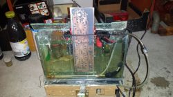
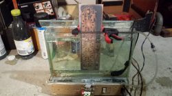
//20231221_203801.jpg 20231221_203808.jpg
length of 1 led cycle 778us
9. Buttons
I did not place the buttons permanently on any of the above boards because I had no idea where they were supposed to be. So I designed a third board with buttons (3 buttons, 4 spare), connected to the previous one with a cable.
I wanted to use regular tact switches, but I didn`t have 10mm long ones at hand, so I used nice Connfly isostats. The isostats I had were bistable, and I needed monostable ones. Here again, as a curiosity, I will say that it was enough to "push" the C-shaped metal wire outwards to conjure up monostable ones from bistable ones.. There are also 10n capacitors on the board to physically eliminate the phenomenon of contact vibration.
* The first button turns on/off the LED backlight
* The second button changes the time display format HHMMSS / HHMM
* The third button is used to set the time (after pressing it, button 1 selects one of the 6 digits, button 2 changes its value 0-9; pressing button 3 again accepts the time change)
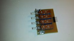
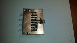
//20231229_120917.jpg 20231229_120925.jpg
10. Nixie boost converter .
After assembling everything, everything seemed to work, but the Nixie lamps were much too dark compared to the LEDs. Unfortunately, the converter using a single NPN MPSA 42 transistor was unable to produce more than about 1mA of current, which was definitely too little for 6 lamps.
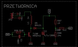
//mpsa_stepup.png
Since the time to give the gift was pressing, I didn`t want to experiment anymore and I used the "proven" converter design from https://threeneurons.wordpress.com/nixie-power-supply/, based on the N-MOSFET IRF740 and the MC34064 system.
It would probably be enough to just replace the NPN with N-MOSFET in my board and add a transistor to control it (so that the mosfet gate could not be controlled directly by 5V from the microcontroller, but could be fed 9V to it through the transistor).
But in order not to reinvent the wheel, I limited my contribution to using the diagram from the above website and based on it I designed a mini-board with a converter, which replaced the existing, inefficient one. The difference in operation is immediately visible, the new one gives 20 mA without any problems. The lamps shined at full power.
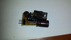
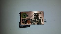
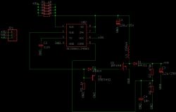
//20231229_104705.jpg 20231229_104710.jpg mosfet-sch.png
11. Housing
The last, and most important from an aesthetic point of view, element of the design is the casing. Makers encase this type of clocks in wood and glass. However, I chose plexiglass due to the lack of carpentry facilities (and my attempts at cutting glass with an oil knife were, to put it mildly, average).
So I ordered 6 pieces of cut-to-size plexiglass. The recipient of the gift is crazy about the color black, so I chose graphite-colored smoked plexiglass (semi-transparent, allows about 20% of light through). Only the front glass is made of transparent plexiglass.
I glued the bottom, top, left and back boards with cyanoacrylate. I connected the right and front ones with M2 screws to make it possible to disassemble them if necessary. I drilled the large holes for the buttons and the power plug with a stepped conical drill at low speed.
I haven`t had much experience with plexiglass before, but I see that it`s a cool material. Only drilling/cutting requires either extremely slow speed or cooling. Otherwise it melts and smells like a dentist`s. And maybe if it wasn`t so electrified and didn`t attract all kinds of dust.
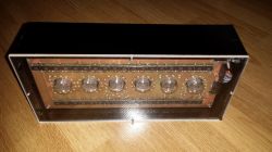
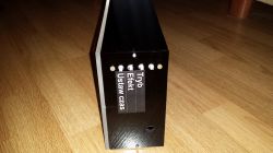
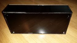

//20231229_154752.jpg 20231229_154801.jpg 20231229_154808.jpg 20231229_153133.jpg
12. Software
I defined such a nice bit structure
#define COLOR_LEVELS_BITS 2

struct rgb_t {
	uint8_t r : COLOR_LEVELS_BITS;
	uint8_t g : COLOR_LEVELS_BITS;
	uint8_t b : COLOR_LEVELS_BITS;
	uint8_t a : COLOR_LEVELS_BITS;
};
thanks to which each component can take 4 different values and I can encode 64 colors on one byte.
The main variable storing the state of what I want to display on the diodes is the buffer
#define LED_COUNT 96
volatile struct rgb_t leds[LED_COUNT + 1];
thanks to this, if I want to set which diodes should be lit - just set the appropriate components of a given diode, e.g. turning on the LED10 in yellow:
leds[10].r = 3;
leds[10].g = 3;
leds[10].b = 0;
Initially, the idea was that counter 0 reports an interrupt at least 540 (60 * 3 * 3) times per second and
* after 1 request, we turn on the R component of all diodes if its component R = 1,2,3 in the buffer
* after the second request, we turn on the R component of all diodes if its component R = 2.3 in the buffer
* after the third notification, we turn on the R component of all diodes if its component R = 3 in the buffer
* after the 4th request, we turn on the G component of all diodes if its component G = 1,2,3 in the buffer
* after the 5th notification, we turn on the G component of all diodes if its component G = 2.3 in the buffer
* after the 6th notification, we turn on the G component of all diodes if its G component = 3 in the buffer
* after the 7th request, we light the G component of all diodes if its B component in the buffer = 1,2,3
* after the 8th request, we light the G component of all diodes if its B component in the buffer = 2.3
* after the 9th request, we turn on the G component of all diodes if its B component = 3 in the buffer
Thanks to this, if the component:
=0 - the diode is on for 0/9 of the time
=1 - the diode lights for 1/9 of the time
=2 - the diode lights for 2/9 of the time
=3 - the diode lights for 3/9 of the time
(lighting time proportional to the component value and you can actually get 64 different colors).

//timer1.png
However, even when turned on only 1/9 of the time, the diodes were too bright compared to the Nixie lamps (I used 330R resistors for the diodes, which forced a current of 10mA for the R diode and 5mA for the G/B diode.
To dim the LED world, I added additional dead periods in which none of the LEDs are lit. I also had to increase the counter frequency to 1953 Hz (16MHz / prescaler 32 / overflow every 256 cycles).
The counter frequency must be selected so that a single color does not flash less than 60 times per second - otherwise unpleasant shaking will be visible.
The nixie tubes are also multiplexed in the same interrupt.
Real-time clock support
The PCF8563 clock uses the I2C protocol, but hardware implementation was not possible because the SCL (PD0) line is used as USBD+ in the V-USB driver, so I had to write a simple software implementation.
13. Final result
After two months of work, I think it worked. In the attached video you can see the flashing, but in reality it is of course not there. And although a real smile cannot be bought or made, the recipient seemed to like it.
KCD
Cool? Ranking DIY


