 .
.
Here I will present an interesting RGBCW lamp driver with a communication protocol very similar to the WS2812B diodes. I became interested in the subject at the request of a reader from Germany, who even sent me a "smart" lamp with this very driver so that I could try to decrypt it and run it in my environment. The aim, of course, was to make it cloud-free. We started the adventure by reverse-engineering, although after we had already decrypted some of the communication, someone else from the readers shared the catalogue note, so things got simpler too. But one step at a time...
This topic is the result of a thread from Elektroda.com:
OpenBeken Driver Connection Issues with RGBIC SM15155E and BK7231N in Smart Wall Lamp .
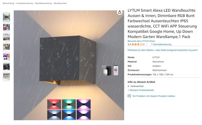
SM15155 is used in at least one of the Tuya lamps available to buy online:
 .
.
It can be found under LYTLM Smart Alexa LED Wandleuchte Aussen & Innen, Dimmbare RGB Bunt Farbwechsel Aussenleuchten IP65 wasserdichte, CCT WiFi APP Steuerung Kompatibel Google Home, Up Down Modern Garten Wandlampe,1 Pack . The brand is allegedly LYTLM .
The lamp itself looks quite good, there is something to fight for:
 .
.
Stage 0 - hardware interview
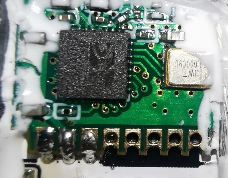
The reader initially already reported that the SM15155 is used in the lamp with the BK7231N module. Additionally, he noted that it is connected to P16 of the BK7231N, this pin is known to be the data output of the hardware SPI port:
 .
.
The other two pins in the picture are ground and power.
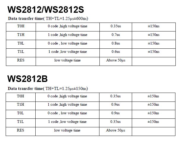
This has already lit the green light for me - this is probably a WS2812B style controller. The WS2812B also uses P16, as it too is controlled by a single signal that requires very precise timing. It's hard to get such timings in software, so a clever use of the SPI port is often made - choosing the bits of the bytes sent so that they form the signal expected by the WS2812B:
 .
.
At some point, I will also address this topic separately.
Step 1 - data capture with logic analyser .
The reader then shared with us just the batch from the WiFi module from inside. There was a BK7231N in there. We simply uploaded this batch to one of our modules with P16 out:
How to access the hardware SPI port on the CB2S? We solder P16 (MOSI) to the QFN .
We used our BK7231 development board for this:
[Youtube] How to make a BK7231 development board - NodeMCU ESP8266 conversion
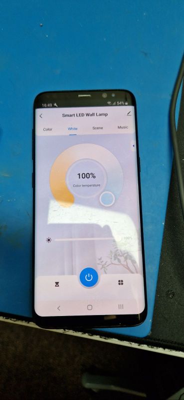
We managed to pair this with Tuya:
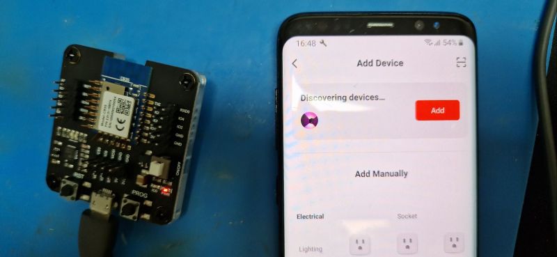 .
.
 .
.
We started to control the 'lamp' via the Tuya app, setting different colours and at the same time capturing data on P16 with our Sigrok analyser:
Reverse engineering an unknown I2C protocol with the Sigrok analyser using an LED controller as an example .
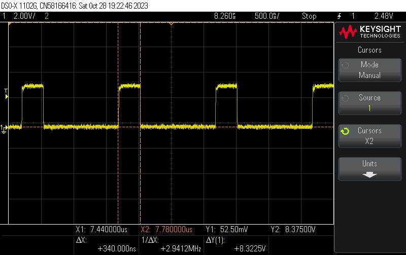
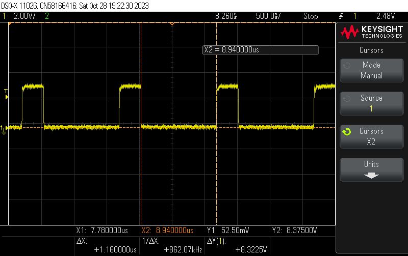
A glance with an oscilloscope already shows the timings:
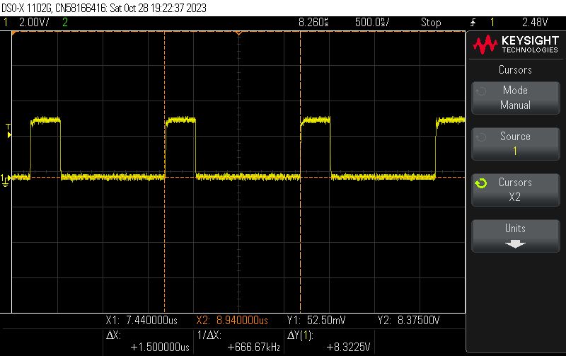
 .
.
High state 340ns, low 1.16us, this is reminiscent of the WS2812B. Not ideal, but maybe...
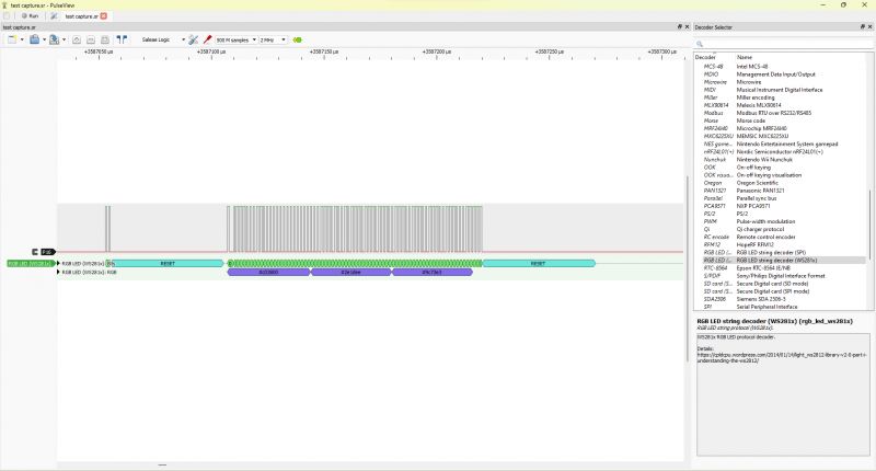
The PulseView analyser, on the other hand, showed that although the timings resemble the WS2812B, the number of bytes seems to be different. Also, the meaning of the bytes themselves seems to disagree.
 .
.
Step 2 - first impressions of the protocol .
Due to the suspicion that this is essentially the same way of communicating as the WS2812B (similar timing) but a different meaning of bytes, I modified the WS2812B PulseView decoder script so that it decodes separate bytes:
Code: C / C++
Immediately better:
 .
.
You can see that the frame is 14 bytes long.
Now you can collect some data....
Step 3 - analysing the collected data .
I compared the data collected for the different colour settings. This lamp is of the RGBCW type, meaning it can operate in either colour mode (red, green, blue) or white colours (cold and warm white). Data analysis confirmed this. An example package for the red colour is:
FA000000000000000000739CE71F
For green, on the other hand, other bits are lit:
00006200000000000000739CE71F
I observed that when we change the value of a given colour the corresponding pair of bytes changes. It can therefore be concluded that the split is as follows:
0000 0000 0000 0000 0000 739CE71F
First we have five 16-bit colour values, and then there are some additional four bytes (perhaps mode configuration or current limits).
Now it remains to test this in practice....
By the way, I didn't detect any checksum here, and already once a single sum with another LED driver caused me a problem:
Reverse engineering an unknown I2C protocol with a Sigrok analyser using an LED controller as an example .
Step 4 - lamp in practice, WiFi module
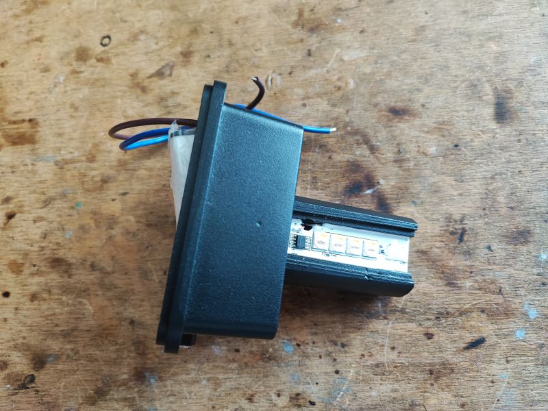
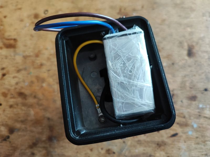
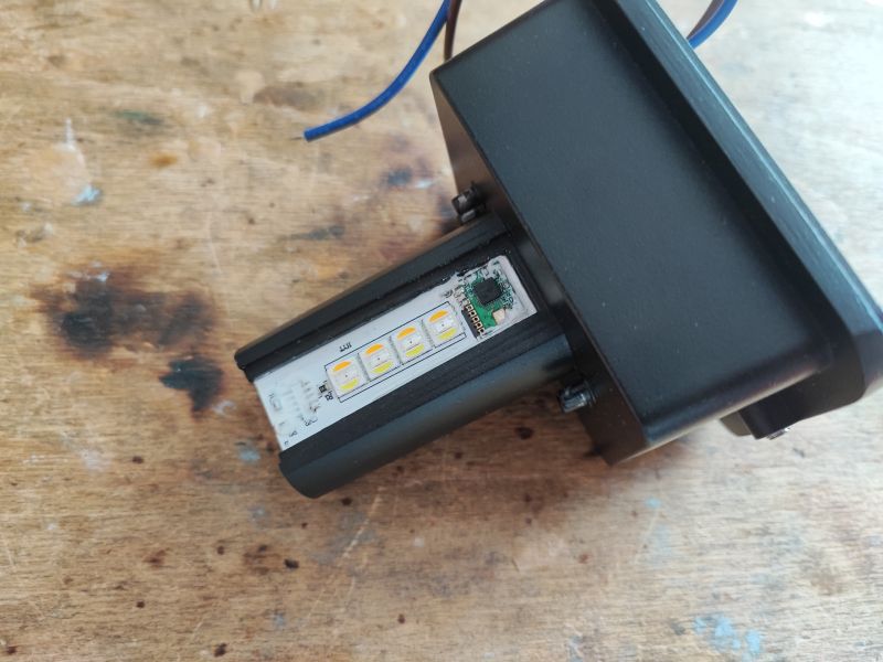
At this stage it would be useful to have this lamp physically at home. Remotely it is difficult to test it. Fortunately, there was an option here too - just a reader sent me this lamp. Due to transport costs, I received the base alone, without the lampshade:
 .
.
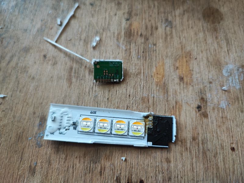
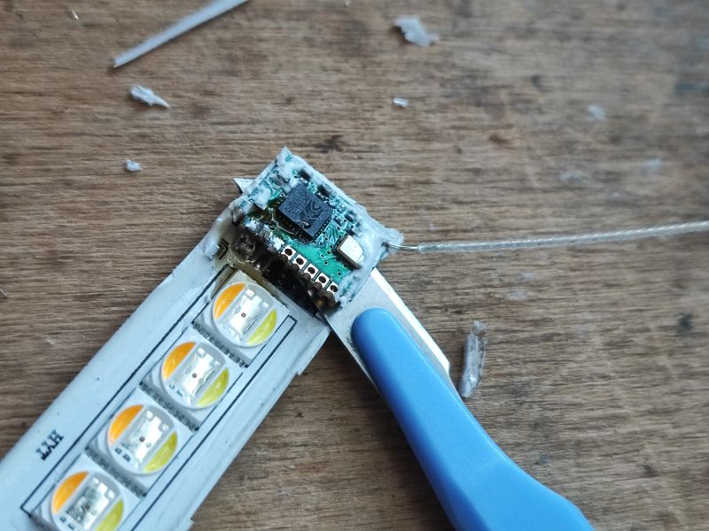
I quickly took to disassembling the whole thing, also to check what kind of WiFi module was sitting there. Neither of the two LED boards were firmly glued to the rest of the lamp, and the module was easily soldered off too:
 .
.
The WiFi module is FL_M129_V3 (BK7231N), dated 2021-12-17, and was worth soldering as it has signed leads on the underside:
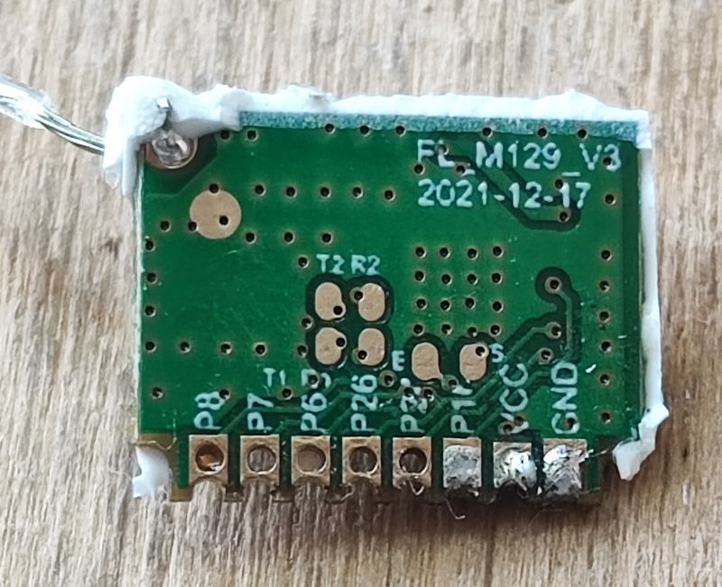
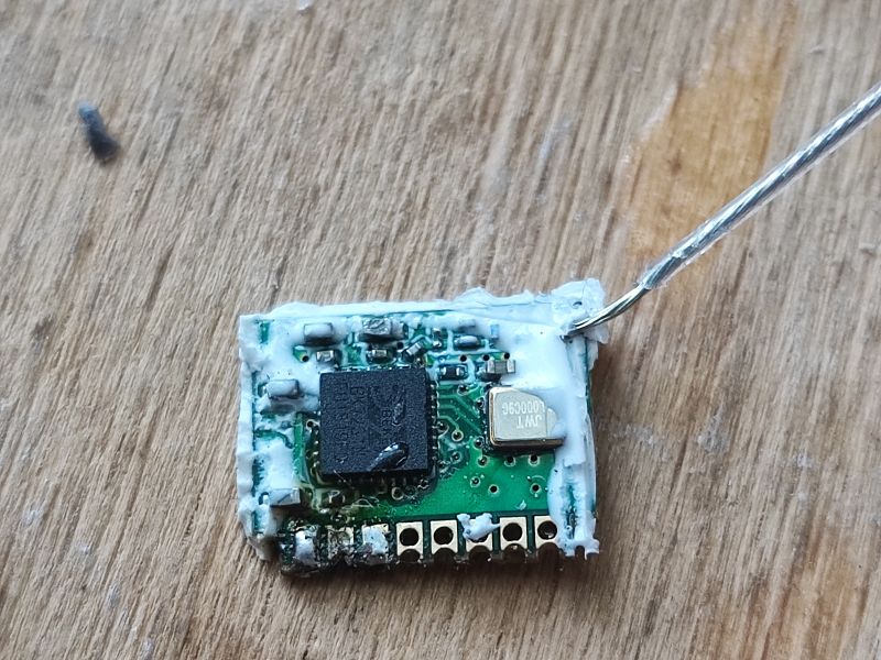 .
.
I started by changing the batch. I uploaded my OpenBeken in there:
https://github.com/openshwprojects/OpenBK7231T_App
According to the flasher instructions:
https://github.com/openshwprojects/BK7231GUIFlashTool
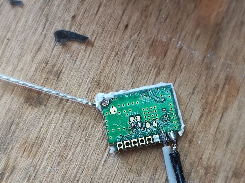 .
.
In the photo above you can see where the power (3.3V), ground, RX and TX are.
Flashing:
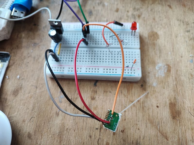 .
.
Circuit assembled for test, without cooling (you have to be careful with this to avoid overheating the LEDs):
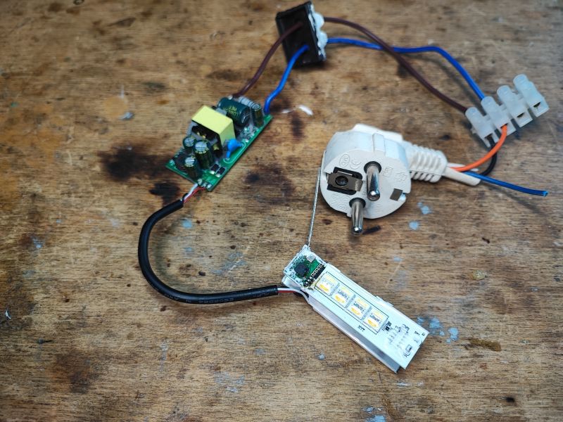
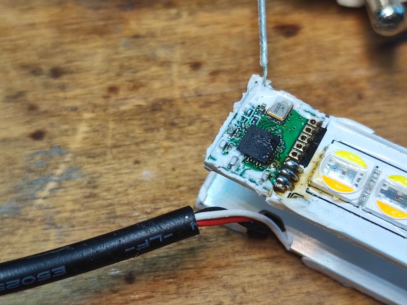
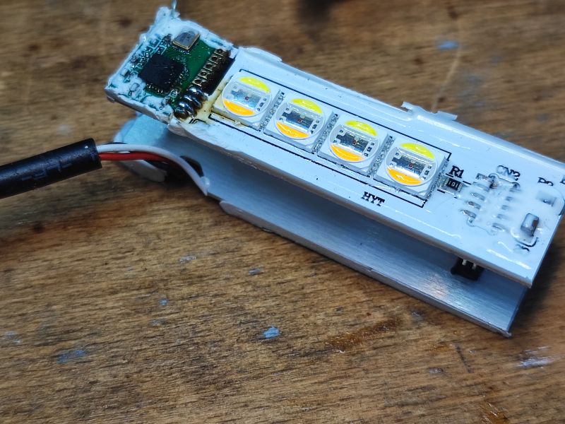 1fcb1fc29f
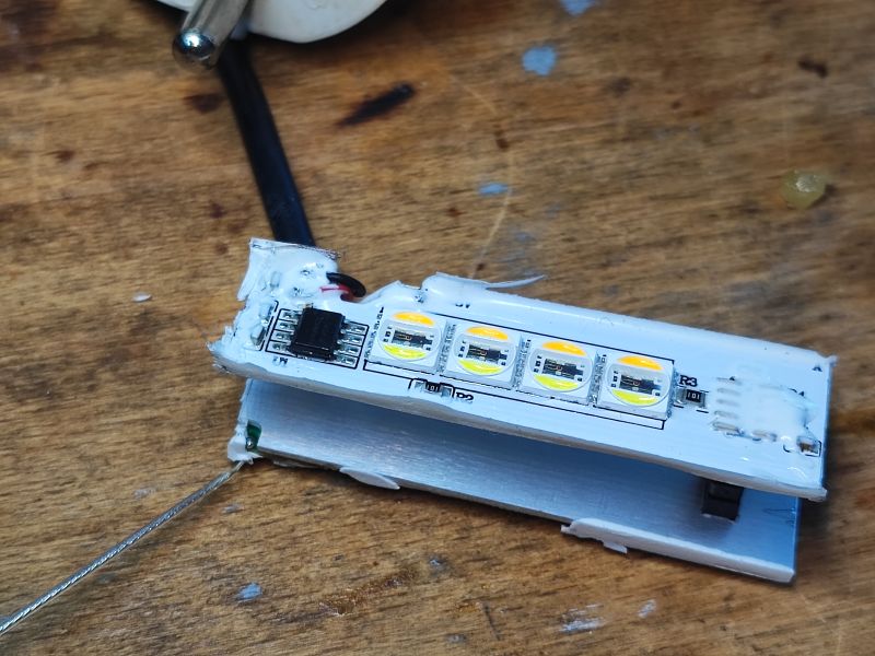
Step 5 - practical test on WS2812B controller .
At the previous stage, I established that the byte sending itself is compatible with the WS2812B, so also with, for example, the SM16703P supported by my software. Only the number and meaning of the bytes is different. This means that I can use my existing SPI-based WS2812B driver to send an artificially prepared frame for the SM15155.
OpenBeken supports scripting, so based on my earlier analysis I prepared a script that sends packets that I suspect will set the next LED colours.
I was hoping that there was no checksum in this packet, although I don't know the meaning of the last bytes....
Here is my script:
startDriver SM16703P

SM16703P_Init 5

again:

SM16703P_SetRaw 1 0 FF000000000000000000739CE71F00
delay_s 1
SM16703P_SetRaw 1 0 0000FF00000000000000739CE71F00
delay_s 1
SM16703P_SetRaw 1 0 00000000FF0000000000739CE71F00
delay_s 1
SM16703P_SetRaw 1 0 000000000000FF000000739CE71F00
delay_s 1
SM16703P_SetRaw 1 0 0000000000000000FF00739CE71F00
// offf
delay_s 1
SM16703P_SetRaw 1 0 00000000000000000000739CE71F00

goto again
The command SM16703P_SetRaw has always been to just blindly send bytes to the WS2812B for quick colour setting, but here it turned out to be like that too. That null byte at the end can be ignored.
The result:
Success! Everything works, now it's time for the dedicated driver under SM15155.
Step 6 - code integration .
This paragraph is no longer so important. I simply added the driver for the SM15155 based on separate communication via SPI for the WS2812B to my software here and hooked it up to the other RGBCW drivers such as SM2135, BP5758, etc. This lamp doesn't have "per pixel" colours, it just globally sets one colour, so the logic fits with SM2135 and similar.
Here is a glimpse of my code:
Code: C / C++
My tests have shown that this particular product does pick up 8-bit values though, I don't know what the other 8 bits from each tube are for. I will have to test it some more.
Step 7 - final test .
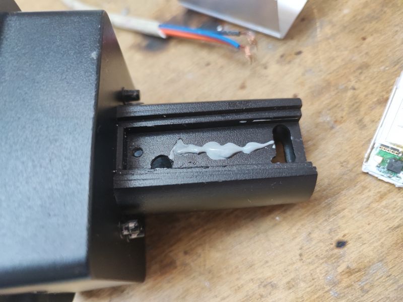
Since the base works, the lamp can be put together. I took the opportunity to add paste between the LED plates and the metal housing:
 .
.
A short test and everything works:
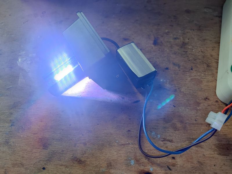
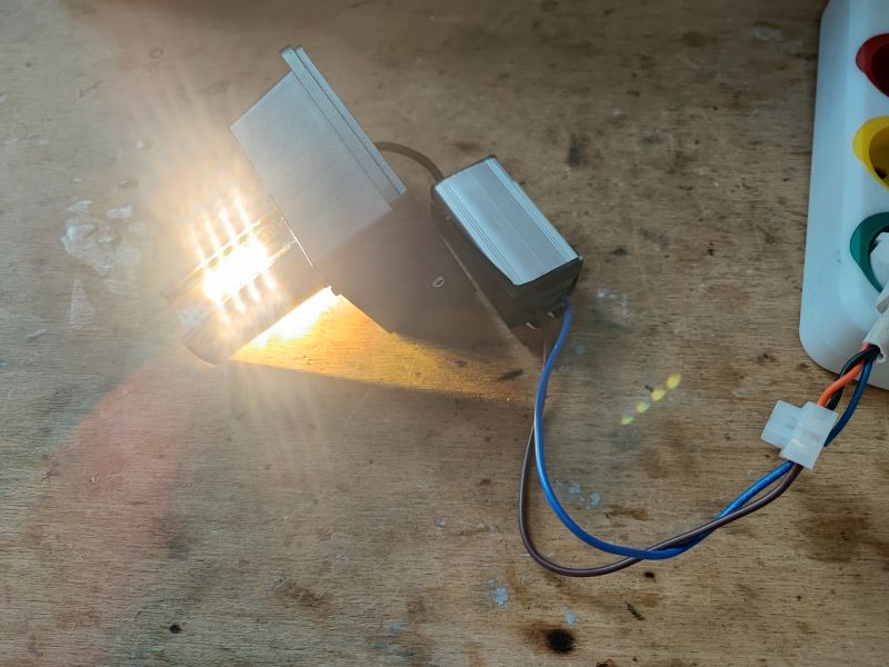
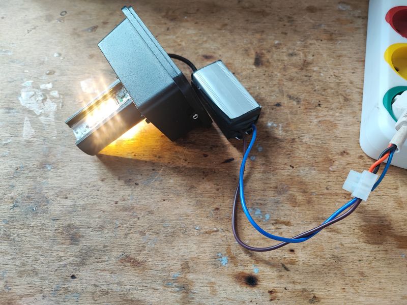
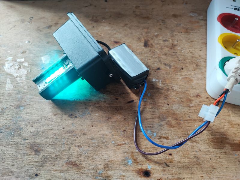
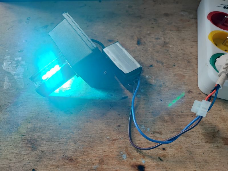 .
.
The lamp now correctly displays the control panel on the OBK home page and can be paired with Home Assistant.
Additional - power supply
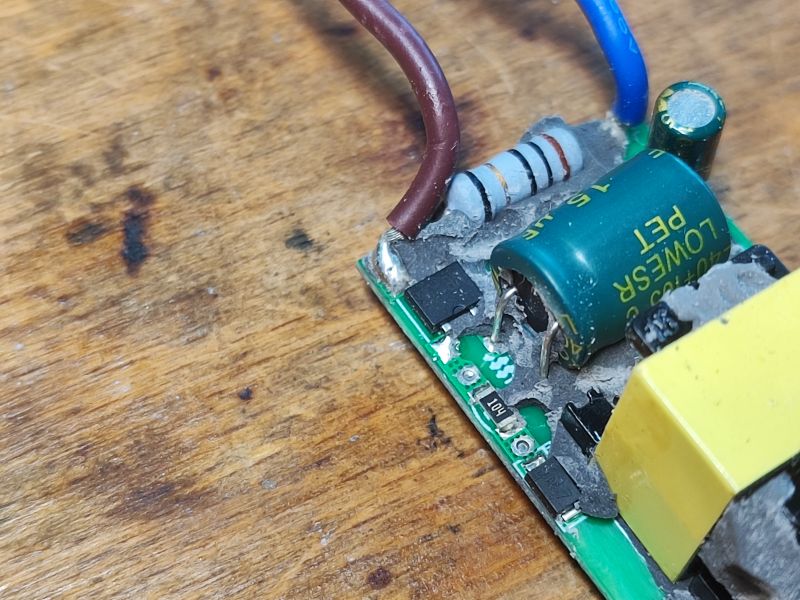
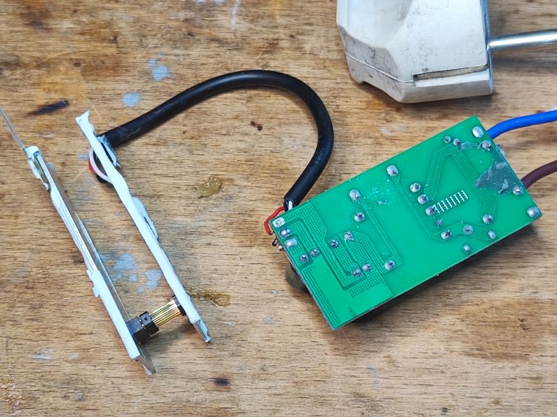
I took the opportunity to take an interest in the power supply module:
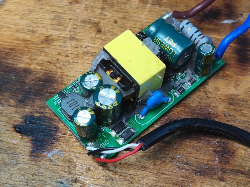
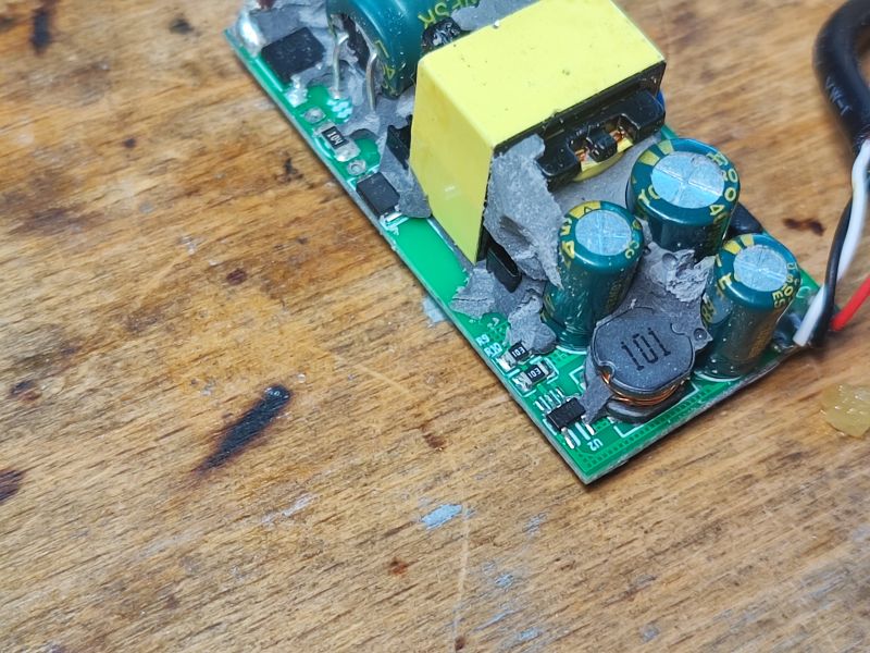
 .
.
The power supply first creates the voltage for the LEDs, and then has a separate step down inverter on the secondary side generating 3.3V for the WiFi module. What exactly the flyback inverter controller is in there, I don't know.
Additional - catalogue note .
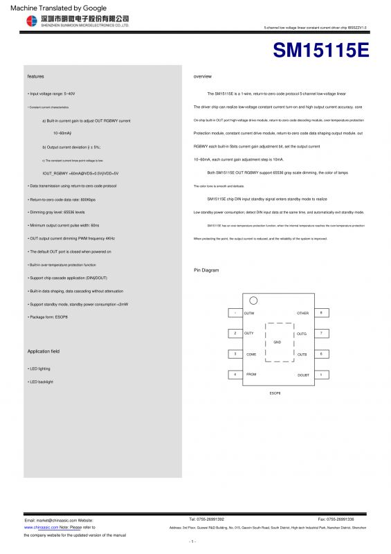
There was no this catalogue note available online when my colleague @DeDaMrAz and I searched for it, but then someone at our forum specifically registered to share it with us. This might clarify for us the meaning of the last bytes.
First page - general information. This protocol is called "1-wire, return-to-zero", I didn't even know. Operating on voltages from 5 to 40V. 16 bits of colour resolution (that's weird, I thought it was 8 though, I'll check it):
 .
.
And yet the SM15155 can be cascaded.
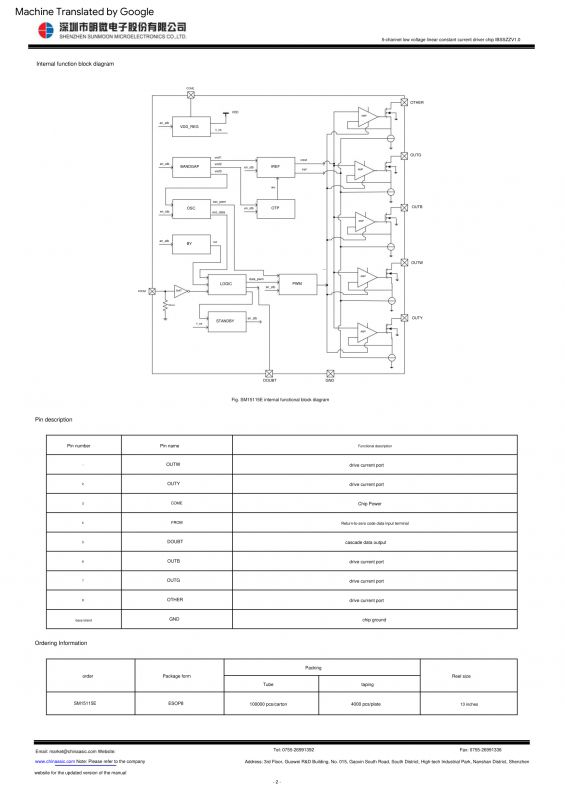
Internal construction:
 .
.
There are five constant-current LED drivers inside.
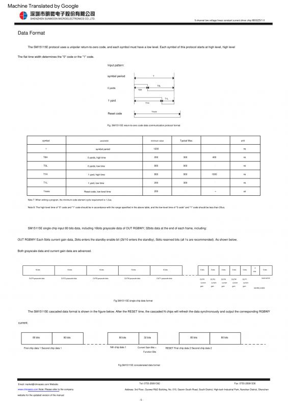
Timings, communication protocol - fairly compatible with WS2812B:
 .
.
That is, however, there are 16 bits per channel, 5 channels and then five times 5 bits each (current settings), 2 standby enable bits and 5 unused bits.
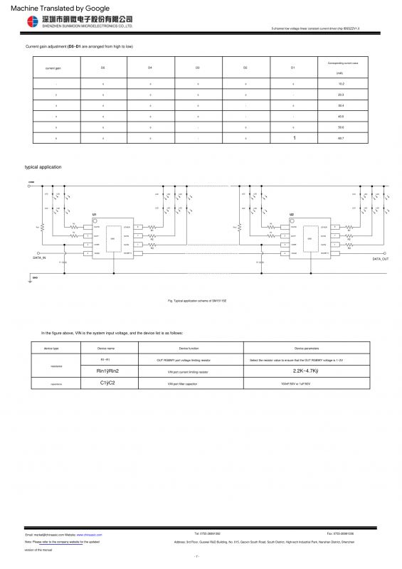
This is what the cascading of the SM15155 looks like:
 .
.
Addition - is how to finally run this driver in OpenBeken? .
To start the SM15155 in OpenBeken, simply add the command to the autostart:
startDriver SM15155
Alternatively, colour mapping can also be performed with the LED_Map command. Nothing else is needed. The rest will work automatically, pairing with HA will also work itself as with other devices.
Summary .
The lamp was successfully commissioned and my SM15155 driver (although incomplete) is probably the first open source driver for this circuit. We couldn't find the datasheet at all, it only appeared when one of its owners took pity and agreed to share it with us.... We already had the base decrypted by then, but the meaning of the last bytes made it clear to us after all. Nonetheless, we probably would have guessed it without that too - separately the brightness levels and separately the current limits are analogously sent in, for example, the BP5758D chip, so such a division is not surprising to me. The enable bit I would also have discovered by trial and error, and in the current driver I don't even use it (although I probably should - I'll rework it).
In summary - the operation was successful, the patient lit up. Another IoT device can already work with my open source software and by the way we also have another satisfied (I hope) reader from Germany. .
@HalliHalo - thanks for sending the lamp, without your package the development of this topic would not have been possible.
Cool? Ranking DIY Helpful post? Buy me a coffee.


