logo elektroda
logo elektroda
X
logo elektroda

OpenBeken Driver Connection Issues with RGBIC SM15155E and BK7231N in Smart Wall Lamp

HalliHallo 4719 59
ADVERTISEMENT
  • I have a "Smart Wall Light" with
    * Wifi
    * 5CH RGB+CCT
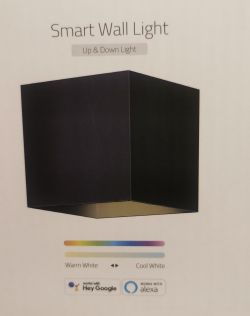
    Modern wall light in a cuboid shape with WiFi support and RGB+CCT control.
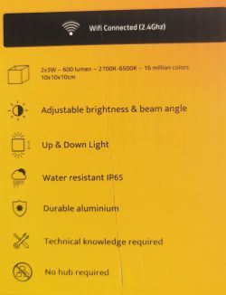
    Technical specifications of a smart wall light with WiFi function on a yellow background.

    Advertisement for an LED lamp with smartphone and voice assistant control features, showcasing colorful home lighting.
    https://www.amazon.de/gp/aw/d/B09N77KL7M


    Tuya_App Informatik:
    Main&MCU v1.1.8

    After flashing with OpenBeken, no function.
    Profile: Tuya Generic - Smart Wall Light v1. 1.8

    I disassembled a lot of the Lamp.
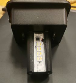
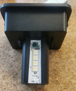
    View of a disassembled smart lamp with visible LED diodes and electronic components.

    I found a
    1x BK7231N
    8x 5in1 CH RGB+CCT (all parallel connected)
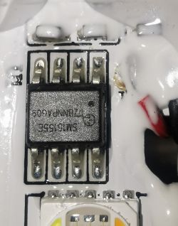
    1x SM15155E

    BK7231N direct by the LED on very small PCB
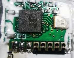
    Image of the interior of a PCB with the BK7231N chip.
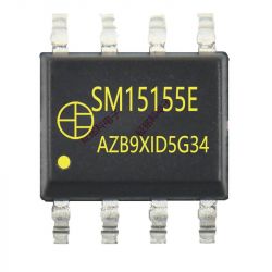
    Close-up of electronic component SM15155E on a PCB.


    BK7231N Pinout on the golden Pins:
    From left to right:
    1: Ground
    2: 3.3V
    3: PIN16 on BK7231N
    4:
    5:
    6:
    7:
    8:


    With OpenBeken Driver "SM16073_DIN" first "connection" to the SM15155E.
    But only one shot and only green light.
    Reboot required after one shot.


    I am happy to assist and help to make this device working together.

    Tuya 2MB dump_flash available.

    Some information in Firmware strings:
    farylink-soc-hzs-5-light-15155-1.1.8-sdk-2.3.1-40.00

    EDIT:
    https://wap-linkage-cn.translate.goog/hangyez...l=auto&_x_tr_tl=en&_x_tr_hl=de&_x_tr_pto=wapp

    Cool? Ranking DIY
    About Author
    HalliHallo
    Level 3  
    Offline 
    HalliHallo wrote 21 posts with rating 3. Been with us since 2023 year.
  • ADVERTISEMENT
  • #2 20778569
    p.kaczmarek2
    Moderator Smart Home
    Welcome to Elektroda @HalliHallo , thank you for submitting teardown.

    From a brief glance, it seems that it is another individually addressable LEDs controller like SM16073, but with different timing, but I am not sure.
    How did this device work before flashing? Were leds individually addressable?

    The usage of P16 for LEDs may not be a coincidence, it's a hardware SPI pin, they are using hardware SPI to push out the pixel data with correct timings.

    It looks like you're saying that only one pixel is working, this may be caused by a timing mismatch.

    We need to know the specific timings of this device.

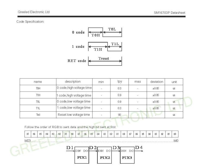
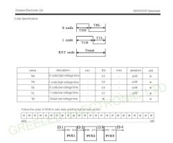
    Please see this section of SM16703 datasheet:
    SM16703P datasheet showing timing code specifications for LED control.
    The linked datasheet of SM15155E does not provide enough information at the current time. It also seems to specify that's a 5 channels driver, so it may not be a SM16703 clone after all.

    Are you sure that only P16 is used for communication?

    If our initial assumption is correct, and it's using a protocol like SM16703 , then we need to either find a datasheet with timing specs or do a capture of data with oscilloscope.
    Helpful post? Buy me a coffee.
  • #3 20778816
    HalliHallo
    Level 3  

    Hey,

    All 8 LEDs are in parallel. All LEDs have the same "brightness" and color.
    No individual LED control for each of the 8.

    All the same. All 8 LEDs are working.

    Original Tuya control:
    On, off, cold white, warm white, RGB color. I think that's the standard.

    I looked into the "source code".
    I only see 3CH and not 5CH control.

    With the existing 3CH driver, it is possible to "switch the LED" to green and make a little brightness correction... But it doesn't fully operate correctly.

    I don't have an oscillation-measuring device... Sorry.

    At the moment, I can't find more datasheets on the internet.
  • #4 20778825
    p.kaczmarek2
    Moderator Smart Home
    Hm okay so I think we have basically two options.
    1. Do you have a 2MB flash dump for this device? Maybe I could try flashing it to BK7231N and using my Rigol to see the waveform on the P16, but I dont know how to even control that device and it may not work anyway because calibration data for WiFi is per-chip... I don't know, but we still might decide to try, I also remember that @DeDaMrAz might have some spare CB3S modules and he also certainly has a scope.
    Do you know which GPIO is used for pairing button?

    2. Well, the second option, maybe even easier one would be for me to get one piece of this device and do the measurement on it.

    We could also try to reach to manufacturer of that LED controller and ask for the datasheet.

    Added after 1 [minutes]:

    By the way, this is confusing:
    Quote:

    No individual led control to each of the 8.

    usually that kind of SPI control is used for individually addressable LEDs...

    EDIT: I also think it's strange there is just single SM15155E, usually those individually adressable chips are connected in chains.
    Helpful post? Buy me a coffee.
  • ADVERTISEMENT
  • #5 20778847
    HalliHallo
    Level 3  

    1. Do you have a 2MB flash dump for this device?

    Yes, I have a full original 2MB flash dump.


    No, I have no more information than I provided. I am an absolute beginner and that chip is so tiny... I need my macro-photography to see lines on the chip.


    Do you know how SM15155E is connected?
    I think PIN 16 goes to the SM15155 (only one in the complete lamp) and that controls all 8 RGBCWWW LEDs in parallel. No individual control of the LEDs. With the original tuya, the complete lamp had one "setting" (on, off, color, brightness, etc.) for all LEDs.

    Sorry, my English is not so good, to explain it better.
    I think that is a stupid technical solution because there is not enough space in the lamp.
    I can take photos or a little "video" for better understanding?

    EDIT:
    The lamp has two "sides", up and down.
    On one side:
    LEDs and electronic component on a PCB.
    4 LEDs and the SM15155E

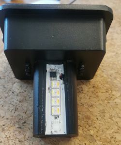
    On the other side:
    LED module with four diodes and an integrated circuit
    4 LEDs and the BK7231N

    And "under" the two PCBs is no space for chips or other things. There are clouds directly on the housing, I think for cooling...


    In the big housing, there is only a power supply (ground, 3.3V, and LED power), connection to 230V Power...
    No more chips or other peripherals...
    I disassembled everything to measure with a simple voltmeter.
    Image of the interior of a lamp housing with wires and mounting elements.
  • #6 20778860
    p.kaczmarek2
    Moderator Smart Home
    Ah wait, I think I understood what's going on here!

    Look:
    Integrated circuit with marking SM15155E with eight pins.

    This chip has 8 pins. So if it has 5 channels, then we have 3 pins left. we also need GND and VDD. So it has only one pin left for control. That's why they used that kind of protocol.

    Ok, now, can you attach 2MB dump?
    Does this device have a button?
    Helpful post? Buy me a coffee.
  • #7 20778872
    HalliHallo
    Level 3  

    You see in my first post detailed photos... That is all what this lamp has... No button, sorry.

    I only attached ".zip" to the binary file, NOT zipped.
    That is the original tuya firmware. I have it dumped with the cloudcutter lightleak android...

    Actually I run on the newest OpenBeken.
    OpenBeken driver SM16.... Can simply control it... Did you need a small video of that possible control-reaction?


    EDIT:
    Other issues I opened regarding this lamp:
    https://github.com/openshwprojects/OpenBK7231T_App/issues/942

    https://github.com/tuya-cloudcutter/tuya-cloudcutter/issues/503

    Probably there is information that is important for you... I am an absolute beginner and I have no idea what information is important for "advanced"...
  • #8 20778910
    HalliHallo
    Level 3  
    OpenBeken
    autoexec.bat

    But, not every boot are "identically".
    Today morning, it starts with red light. After reboot, green as 95% boots. 50% that brightness setting works.

    autoexec.bat:
    delay_s 5

    startDriver SM16703P

    SM16703P_Init 1
    SM16703P_SetPixel 1 0 0 32
    SM16703P_SetPixel 2 0 0 32
    SM16703P_SetPixel 3 0 0 32
    SM16703P_Start
    delay_s 1
    SM16703P_SetPixel 1 0 64 0
    SM16703P_Start
    delay_s 1
    SM16703P_SetPixel 1 0 32 0
    SM16703P_Start
    delay_s 1
    SM16703P_SetPixel 1 0 64 0
    SM16703P_Start
    delay_s 1
    SM16703P_SetPixel 1 0 128 0
    SM16703P_Start
    delay_s 1
    SM16703P_SetPixel 1 0 64 0
    SM16703P_Start
    delay_s 1
    SM16703P_SetPixel 1 0 32 0
    SM16703P_Start


    Hinzugefügt nach 3 [Stunden] 47 [Minuten]:

    I found a link, but I have no Login / WeChat

    https://www.zhanghuanglong.com/dl/detail/Argon_Ghost/874364

    Hinzugefügt nach 11 [Minuten]:

    Found with Google translate:
    SIC protocol intelligent driver chip

    Dimming gray scale: 65536 levels;
    Minimum output current turn-on pulse width: 160nS ;
    OUT PWM output, good color reproduction, PWM frequency 4KHz ;
    Built-in over-temperature protection function;
    Built-in data shaping, data cascade ( DIN→DOUT ) does not attenuate;
    Built-in automatic energy-saving mode, standby power consumption <2mW ;
    Built-in current gain, adjusts OUT RGBWY current 10~300mA ;
    Constant current output, changes in lamp bead voltage difference will not cause changes in lamp bead brightness;
    Supports WIFI , Bluetooth, Zigbee , 2.4G and other control modules.

    App types Three-way five roads chip
    SM15153E
    SM15155E

    Hinzugefügt nach 24 [Minuten]:

    LED Driver Chips That Support all The Mainstream Serial Data interfaces on The
    Marke
    Such as MBI6020、MBI6021、MBI6024、MBI6023、MBI6120、MBI6027、MBI6034、MBI6033、MBI6030、LPD6803、LPD8806、LPD1886、LPD1882、TM1803、TM1804、TM1829、TM1812、TM1914、TM1925、TM1926、TM1905、TM1905、TLS3001、TLS3008、TLSGY01、MY9221、MY9231、MY9291、MY9234、WS2801、WS2811、WS2812B、 WS2818A、WS2816、CX808、P9813、P9823、P9883、AP102、AP104、GS8206、GS8208、SM16716、BS0815、BS0901、BS0902、UCS1903、UCS1904、UCS1909、UCS1912、UCS2903、UCS2904、UCS2912、UCS8903、UCS8904、UCS9812、UCS3903、UCS5603、UCS2603、UCS8603、TI5971、TI5973、TI59731、GW6201、GW6205、GW6230、GW6236、GW6212、GW6209、GW6206、GW6209、GW6212、GW6230A、GW6211、GW6803、GW6606、SM16711、SM16716、SM16703P、SM16704P、SM16736、SM16803P、SM16804P、SM16813P、SM16814P、SM16823E、SM16824E、SM16825E、SM15155E、ICND2110、HX5011、ZQ1111、 LX1603、LX1203、HBS1916、HBS1910、HBS1510、HB200B、KW1203A、CX808、DM412、DM413、DM621、MC2002、MC2.0、PM1.0、MT1809、MT1815S、MT16703 etc。


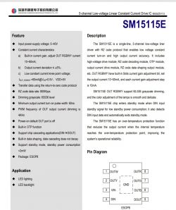
    Screenshot Datasheet

    Return to zero protocol?
    RZ protocol?
    Technical documentation for the SM15115E constant current driver chip.
  • #9 20784246
    HalliHallo
    Level 3  

    Can I get a local development and create my own OTA files for testing?

    800 kb/s = timing?
    8-bit for leveling
    5 ch...

    Can I start with that and try the sm16073 driver?
  • #10 20784319
    p.kaczmarek2
    Moderator Smart Home
    Thanks for the info. You can fork our repository and open a pull request, the binary files will be created automatically. You don't need local setup for that.

    I will also try to look into that soon, maybe flash the bin on the other BK7231N device and look at the waveform with oscilloscope.
    Helpful post? Buy me a coffee.
  • #11 20785515
    HalliHallo
    Level 3  
    Have you seen the short Datasheet in the previous answer attachment?
    Is that enough information or did you need more detailed information, how the data is transfered?

    Than I will try to contact the company.
  • #12 20785572
    p.kaczmarek2
    Moderator Smart Home
    The attached datasheet reads:
    
    Data transmission using return-to-zero code protocol
    Return-to-zero code data rate:800Kbps
    

    It indeed seems to provide some basic information, but I would like to see the details.
    So far I've found:
    https://en.wikipedia.org/wiki/Return-to-zero
    Helpful post? Buy me a coffee.
  • ADVERTISEMENT
  • #14 20789046
    p.kaczmarek2
    Moderator Smart Home
    The following document seems to describe the SPI transmission, which is not used in case of your device. I know that we are internally using SPI MOSI pin to drive SM16703, but that's a different thing.

    Added after 3 [hours] 52 [minutes]:

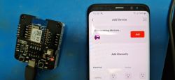
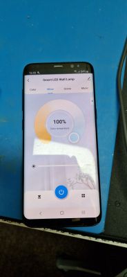
    Ok @HalliHallo , we have flashed your 2MB dump on our CB3S with @DeDaMrAz and will try to scope some things:
    CB3S module connected to a computer and a smartphone with a device-adding app Smartphone displaying an app for controlling a smart LED lamp, showing color temperature settings.
    We will hopefully know more information soon. Now we need to get access to P16... like here:
    https://www.elektroda.com/rtvforum/topic4005865.html

    Added after 1 [hours] 3 [minutes]:

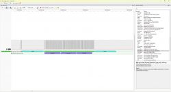
    Screenshot from PulseView software showing an analysis of an RGB LED (WS281x) signal using a decoder.

    Added after 39 [minutes]:

    first capture, open in PulseView
    Helpful post? Buy me a coffee.
  • #17 20789559
    p.kaczmarek2
    Moderator Smart Home
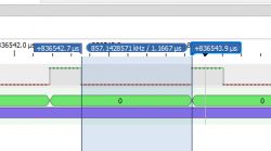
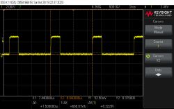
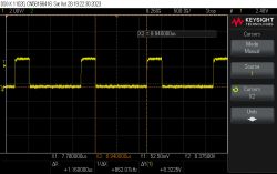
    340ns and 1160ns ... or rather 350ns and 1150ns I would say.
    Here are WS2812B specs:
    Table showing data transfer times for SM16703P.
    Kinda close...
    Here is SM16703P:
    Specification of coding and reset times for SM16703P.
    Hmm the timings does not match too well, I will have to adjust our drivers to generate a closer timings.
    Helpful post? Buy me a coffee.
  • #18 20791000
    p.kaczmarek2
    Moderator Smart Home
    PulseView decoder work....
    LED signal graph with color coding for WS281x and SM1515E LEDs.
    I have ported WS2812 one to SM15155E
    Code: Python
    Log in, to see the code
    Helpful post? Buy me a coffee.
  • ADVERTISEMENT
  • #20 20795751
    HalliHallo
    Level 3  
    Wow, so much informations.

    I will try to understand, but I am no eletrican...

    SM15155E = 5ch RGBCY (RGB +WW +CW)
    SM15153E = 3ch RGB

    I can try your code, I can only ota-update the light.
  • #21 20795923
    p.kaczmarek2
    Moderator Smart Home
    We're still working on it, we know the timings and we have a per-byte decoder, but we don't know the meaning of individual bytes yet.
    Helpful post? Buy me a coffee.
  • #22 20811754
    HalliHallo
    Level 3  
    Can I try with "try & error" the association?
  • #23 20813253
    steppyvanbeek
    Level 1  
    Any update? Been waiting for this one for months
  • #24 20825432
    HalliHallo
    Level 3  
    Hey,

    any update here or something else, what I can test or do?
  • #25 20825633
    wolfieeewolf
    Level 11  
    I'm thinking these are SMD 5050 led's so ws281X timing will not work.

    Have you tried running the strip with WLED? That might help work out what protocol you need to use.
  • #26 20826597
    HalliHallo
    Level 3  
    I can only update over ota.

    Where is a tutorial to update over ota from openBeken to wled and back?

    Than I can try ist.
  • #27 20827693
    wolfieeewolf
    Level 11  
    You can't flash WLED on the chip you have. You will need to buy an ESP-compatible board like a nodeMCU and use that. There are lots of tutorials on YouTube on how to do that. Once you have your nodeMCU flashed with WLED hook up your strip and test it.
  • #28 20836214
    HalliHallo
    Level 3  
    Strip? I have this Smart Wall Lamp, see I my first posts
  • #29 20836516
    wolfieeewolf
    Level 11  
    HalliHallo wrote:
    Strip? I have this Smart Wall Lamp, see my first posts


    On your wall lamp, you will find this

    White glue covering a connector section on an LED board.

    Where the red circle is, you will need to carefully remove the white glue and see if there are any pads underneath. They will most likely look like this

    LED strip with red outline showing connectors.

    If your pads look like the ones above, then you have non-addressable RGB CCT LEDs and can follow this to see if you can get them working. But you do run the risk of overloading the LEDs if not done properly, so I would advise against it if you're new to this.

    If you find that there are data, clock, and voltage pads, then you have addressable LEDs and should follow this. That will get you started, but again, if you are new to this, you run the risk of overloading and killing your LEDs, so read everything carefully.

    If you can't find any pads at all and only the power and ground wires, then that is something WLED can't do. Two-wire controls are very tricky and most likely almost impossible to hack. It would require programming special code just to run the LEDs. Something like the way these LSC string lights are controlled.

    I really don't think that those LEDs are controlled like that, but if they are, then I have no idea what you could do to get them working. Without the original firmware dumped straight off the chip, you might never be able to get them working, and even then, it would be a shot in the dark.

    I highly doubt your LEDs are addressable and are most likely controlled via PWM.
  • #30 20836825
    p.kaczmarek2
    Moderator Smart Home
    His LEDs are controlled via single GPIO like the ones that are addressable, but I don't think ESP32 will help, because SM15155E protocol is not yet fully known. So there are no open source drivers for that yet. We've done first stage of reverse engineering, but there is more work to do.
    Helpful post? Buy me a coffee.

Topic summary

The discussion revolves around connection issues with a Smart Wall Lamp utilizing the OpenBeken driver, specifically with the RGBIC SM15155E and BK7231N components. The user reports that after flashing the device with OpenBeken, the lamp ceased to function correctly, despite previously operating with the Tuya app. The lamp features 8 parallel-connected RGB+CCT LEDs, controlled by the SM15155E driver. Participants in the forum suggest that the problem may stem from timing mismatches in the driver, as the original control allowed for basic functions like on/off and color changes without individual LED control. Various troubleshooting steps are discussed, including the need for specific timing data and potential reverse engineering of the SM15155E protocol. The community is actively working on developing a compatible driver and analyzing the device's communication signals to restore functionality.
Summary generated by the language model.
ADVERTISEMENT