logo elektroda
logo elektroda
X
logo elektroda

Controlling the power regulator with the ESP32 - what to replace the buttons with?

iksrowaj 561 10
ADVERTISEMENT
Treść została przetłumaczona polish » english Zobacz oryginalną wersję tematu
  • #1 21141028
    iksrowaj
    Level 3  
    Dear forumers.
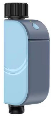
    I have such a power regulator:
    Controlling the power regulator with the ESP32 - what to replace the buttons with? Controlling the power regulator with the ESP32 - what to replace the buttons with? .
    I would like to control this via ESP32.
    What to replace the buttons with?
    Transistor? optocoupler? SSR? Due to the switching speed, a standard mechanical relay is not an option.
    Best regards
  • ADVERTISEMENT
  • #2 21141072
    Anonymous
    Level 1  
  • ADVERTISEMENT
  • #3 21141080
    iksrowaj
    Level 3  
    >>21141072 .
    A response of the type: I will write something there and "accept 2 points". Nothing comes of it.
    Replace button, with button?
    Nobody writes about acceleration. Instead, it is written that it is to be controlled by ESP, and due to the clicking every, say, few seconds, a mechanical relay is out.
  • ADVERTISEMENT
  • #4 21141140
    Anonymous
    Level 1  
  • ADVERTISEMENT
  • #5 21141164
    JacekCz
    Level 42  
    emarcus wrote:
    Are you sure you know what you want?


    I suppose, he wants to be the winner in the conversation.
    You know, such times, the lack of logic wrapped up in so-called "assertiveness", courses, training, those climates ....
  • #6 21141174
    iksrowaj
    Level 3  
    This forum is starting to go down the drain.
    Like a poodle.

    Moderated By ArturAVS:

    3.1.9. Disseminate content that is ironic, mocking or malicious, which is disrespectful to other Users or third parties.

    .
  • #7 21141182
    ArturAVS
    Moderator
    You already have the executive member (triac, optotriac and simple transformerless power supply). If there is to be an ESP32, what's the problem of doing all the handling on it? The original power supply will be too weak for the ESP though.
  • #8 21141212
    karwo
    Level 31  
    There are two options:
    1. build an interface between the ESP and the existing regulator - optocouplers would make sense (power separation), it would be a good idea to reverse engineer the existing regulator from the pushbutton side and see how it is done by the majfrids
    2. add an actuator to the ESP and omit the existing regulator - google ESP+phase regulator (depends on what you want to control).
  • #9 21141256
    iksrowaj
    Level 3  
    >>21141212 .
    The buttons are wired sequentially:
    Down>R8>IO13 of this IC without inscription
    ON/OFF>R15>IO2
    UP>R7>IO12
    Based on other solutions of this type, I suspect this is something like a digital potentiometer.
    When connected to 230V there is +1.2V DC and GND on the buttons
    Controlling the power regulator with the ESP32 - what to replace the buttons with? .
    By design, this is intended to be an interface to the so-called "zero export". The ESP is supposed to poll the EE meter and, in the event of energy export to the grid, is supposed to regulate, say, the power of a heater or something similar.
  • #10 21141329
    ArturAVS
    Moderator
    iksrowaj wrote:
    By design, this is to be an interface for so-called "zero export". The ESP is supposed to poll the EE meter and, in the event of energy export to the grid, is supposed to regulate, say, the power of a heater, or something similar.

    This is what I suspected.

    iksrowaj wrote:
    I suspect that it is something like a digital potentiometer.

    A digital potentiometer makes no sense in such an application, here it is either PWM or phase control (although the optotriac is out of sync with the mains and you can't see the zero crossing detector circuit) or even group control if it is only for heaters. Write the whole operation on an ESP and add phase/group control, on the tape you probably have signals, Vcc, GND, output and zero detection.
    In truth, it's better to redesign the whole thing from scratch.
  • #11 21141404
    karwo
    Level 31  
    iksrowaj wrote:
    Based on other solutions of this type, I suspect it is something like a digital potentiometer.
    .
    That is, the keyboard - 3 buttons are wired to the ADC input of the controller.
    ArturAVS wrote:
    Truthfully, better to redesign the whole thing.

    Again @ArthurAVS is right - better to do it from scratch on ESP, just would need to consider what type of phase/group control would be more beneficial to use.

Topic summary

The discussion concerns controlling a power regulator with an ESP32 by replacing its mechanical pushbuttons. The original regulator uses three buttons wired sequentially to an IC with unknown marking, likely functioning as a digital potentiometer interface with a low-voltage DC supply derived from 230V mains. Mechanical relays are unsuitable due to switching speed constraints. Suggested solutions include using optocouplers for electrical isolation when interfacing the ESP32 with existing buttons or redesigning the control entirely with the ESP32 implementing phase or PWM control for power regulation. The existing regulator appears to use triacs or optotriacs for switching, but lacks zero-cross detection circuitry, complicating synchronization. The buttons are connected to ADC inputs on the controller, indicating a multiplexed or analog input method. Overall, the consensus favors replacing the entire control logic with an ESP32-based phase control system rather than attempting to emulate button presses electronically, as the current design is limited and not optimized for automated control.
Summary generated by the language model.
ADVERTISEMENT