logo elektroda
logo elektroda
X
logo elektroda

ESP32, battery back-up and digital potentiometer amplifier control

czarny8322 3063 33
ADVERTISEMENT
Treść została przetłumaczona polish » english Zobacz oryginalną wersję tematu
  • #1 18248183
    czarny8322
    Level 11  
    Good morning:) .

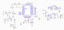
    I would be very grateful for constructive answers:) I am building a radio on an ESP32 with battery backup. The amplifier is a PAM8403 module, for which I would like to adjust the signal power from the DAC by software with a digital potentiometer: X9C103 (one channel). Therefore, I have some questions for the following schematic:

    1. does such a battery backup scheme have the right to work?
    2. I have a separate +5V line (missing on the schematic) - since the ESP32 runs on 3.3V, can I connect the VCC for the X9C103 to +5 and its logic will be controlled from the ESP32 pins without some logic state conversion?

    3. does anyone see any errors in the schematic?

    For all answers thank you in advance.


    ESP32, battery back-up and digital potentiometer amplifier control
    .
  • ADVERTISEMENT
  • #2 18248208
    khoam
    Level 42  
    czarny8322 wrote:
    since the ESP32 runs on 3.3V, can I connect the VCC for the X9C103 to +5 and its logic will be controlled from the ESP32 pins without some kind of logic state conversion?
    .
    No, logic level converters are required.
  • ADVERTISEMENT
  • #5 18248618
    jarek_lnx
    Level 43  
    khoam wrote:
    It may work, but if it's going to work like this for longer, get a spare ESP32.
    The standby ESP can always come in handy :) but I don't understand what you are trying to scare the author of the topic with, damage to the ESP from a device that only has inputs? As long as it doesn't burn up the X9C103 then nothing will happen to the ESP either.
    The logic levels of the X9C103 are TTL, so compatible with the 3.3V CMOS outputs.
  • #6 18248919
    khoam
    Level 42  
    jarek_lnx wrote:
    I don't understand what you are trying to scare the author of the topic with, ESP damage from a device that only has inputs?
    .
    I'm not trying to scare you, just trying to develop good habits ;) The internet is full of so-called fritzing with ESP, which are simple (or rather primitive) circuit conversions from AVR.

    Now for some minor observations:
    1. if during booting GPIO 12 is in the high state , the ESP32 will "hang".
    2. when the ESP32 is booting, there is a short output signal PWM on GPIO 14 and GPIO 15. Will it not interfere?
  • #7 18249781
    jarek_lnx
    Level 43  
    khoam wrote:
    I'm not trying to scare you, just trying to develop good habits
    If you're not scare-mongering, why the comment about a back-up ESP? What did you want to show in the manufacturer's documentation? I don't like vague hints, how is an amateur supposed to guess what problem you are writing about when I don't see any problem. Maybe you thought there was an output from the 5V circuit, but you wrote so vaguely that you could always change your mind and no one would know?

    khoam wrote:
    The internet is full of so-called fritzing with ESP, which is a simple (or rather primitive) circuit conversion from AVR.
    Probably this is the case, but what effect does it have on the circuit we are discussing?
    Good habits means checking the facts, and the facts are that the input of a circuit supplied with 5V will not supply voltage to the output of a circuit supplied with 3.3V, i.e. there is no risk of damage to the ESP. The second fact is that the output levels of a 3.3V CMOS chip (ESP) are within acceptable limits for a 5V TTL-compatible input.

    And coming back to the topic, the divider by 11 before the potentiometer is strange, what should be the maximum signal level at the output?
    Another thing is that the DAC has to work with an offset in order to process audio signals correctly, and if you apply a DC voltage from the DAC to the potentiometer, you will hear crackling during the adjustment, before the potentiometer or before the divider there should be a capacitor to cut off the DC component.
  • #8 18249943
    khoam
    Level 42  
    czarny8322 wrote:
    Does such a battery backup scheme have the right to work?
    .
    The nominal output voltage of the CR2032 is 3V, and given that the ESP32 can draw up to 300mA in 'gusts', this voltage may be slightly less at times. The additional voltage drop on the SS34 (about 0.5V) only makes matters worse. The minimum supply voltage for the ESP32 is 2.4-2.5V, so the circuit will work or not with such a battery supply, and it may also reset periodically. Of course, the values of the logic levels on the ESP outputs will also change then, which you can check in the manufacturer's documentation to which I have already given you a link.
  • ADVERTISEMENT
  • #9 18250398
    jarek_lnx
    Level 43  
    A CR2032 battery might be able to withstand a momentary load of 30mA, but 300mA is not even possible on a short circuit, so such a backup can only work in the case of Hibernation mode and Deep Sleep, when the ESP will have the radio part and the core switched off all the time, leaving RTC and ULP.
    https://lastminuteengineers.com/esp32-sleep-modes-power-consumption/
    https://data.energizer.com/PDFs/lithiumcoin_appman.pdf
  • #10 18250601
    khoam
    Level 42  
    In deep-sleep mode (and its variant "hibernation mode"), power to the SRAM is switched off, so the data stored in it will be lost upon waking up. If you want to "keep" certain information, e.g. the last station you listened to, your list of favourite stations, etc., then such information should be stored before entering deep-sleep mode. This can be done in two ways: storing this data in that part of the SRAM which is part of the RTC chip, or writing it to SPIFFS (Flash memory file system). In the first case, however, this data will be lost when the ESP32 reset is performed, so it is better to use the second method.

    The ESP32 automatically stores information about the current WiFi and BLE network configuration in the RTC SRAM, before entering deep-sleep mode.

    jarek_lnx wrote:
    The CR2032 battery could withstand a momentary load of 30mA
    .
    It will hold more than that, which does not mean it is suitable for powering the ESP32 in normal WiFi enabled operation.
    https://www.dmcinfo.com/Portals/0/Blog%20File...CR2032%20coin%20cell%20battery%20capacity.pdf
  • #11 18253596
    Anonymous
    Level 1  
  • #12 18253609
    khoam
    Level 42  
    FreelancerPL aka Korteks aka o_Tadeusz aka LChucki aka R-MIK wrote:
    I would disagree. Already at 20mA, due to the large input resistance (depends on the manufacturer) there are large voltage drops at even 20mA. Many electronics at 2.4 or even 2.7V no longer work properly.
    .
    This is precisely the information contained in the document I provided a link to in post #10. Using such a battery, with temporary increases in current draw would make more sense with a step-up inverter. I also wrote, agreeing with colleague @jarek_lnx that:
    khoam wrote:
    It will hold more, which does not mean that it is suitable for powering the ESP32 in normal WiFi enabled operation.
    .

    Added at 29 [minutes]:

    @black8322 At the moment, one of the most popular 'battery' solutions for the ESP32 are those that use 18650 Li-ion batteries. Such a solution also allows the ESP32 to work properly in normal WiFi enabled mode. I provide a link to an article where this is described in detail:
    https://www.electroschematics.com/battery-shield/
  • ADVERTISEMENT
  • #13 18257538
    czarny8322
    Level 11  
    Thank you for your replies, and confirmation that it does not need logic state conversion.

    1. battery backup - I only care about remembering the current time (RTC&ULP). From what I've read, assuming the ESP32 will detect a change in voltage, then go into "Deep sleep" mode then the CR2032 should pass the test. There are also LIR2450 rechargeable batteries available at 3.6V - if the regular CR2032 doesn't pass then I'd replace it. Larger 18650 type solutions are unfortunately out of the question as there is no room for them for this project.

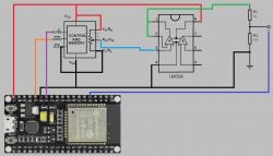
    2 Voltage divider: I downloaded the schematic and library from the following project:
    https://www.xtronical.com/basics/audio/dacs-on-esp32/
    https://www.youtube.com/watch?v=xotWNWUh7i4
    a1e103bb8 .
    Regarding power - the PAM amplifier that is in the project is 2x3W - but I only need 1x1W - I don't have room for large speakers. So perhaps you know of some other circuit/module that I could use?
  • #14 18257620
    TvWidget
    Level 38  
    czarny8322 wrote:
    Battery backup - I only care about remembering the current time (RTC&ULP). From what I've read, assuming the ESP32 will detect a change in voltage, then go into "Deep sleep" mode then the CR2032 should pass the test.
    .
    You are making a logical error. An ESP32 powered by a CR2032 battery will not detect anything. It will stop working.
  • #15 18257644
    czarny8322
    Level 11  
    Are you sure? As far as I know, in the "Deep Sleep" mode I can use the ULP that supports this ADC, with which I could study the change in voltage with which the ESP32 is supplied,

    The other possibility is an external wake up, using some transistor that would simulate a button after a voltage change.
  • #16 18257657
    khoam
    Level 42  
    czarny8322 wrote:
    For all I know, in "Deep Sleep" mode I can use the ULP that runs this ADC, with which I could investigate the voltage change that the ESP32 is powered by
    .
    Yes, the ULP can poll the ADC in deep-sleep mode to determine the voltage value at a particular pin.

    czarny8322 wrote:
    The other possibility is an external wake up, using some transistor that would simulate a button when the voltage changes.835353591d0a
    ULP can be used to wake up the ESP32 when external power returns on the pin monitored by the ADC.
    https://docs.espressif.com/projects/esp-idf/e...ystem/sleep_modes.html#ulp-coprocessor-wakeup

    Added after 1 [minute]:

    Also keep in mind that it's not just the ESP32 that can draw current with battery power in your particular circuit.
  • #17 18257738
    TvWidget
    Level 38  
    czarny8322 wrote:
    it will detect a change in voltage and then switch to "Deep sleep"
    .
    So which mode should the voltage change detection take place in ?
  • #18 18257755
    khoam
    Level 42  
    czarny8322 wrote:
    I, on the other hand, only need 1x1W - I don't have room for large speakers. So maybe you know of some other chip/module that I could use?
    .
    LM386N
  • #19 18257770
    czarny8322
    Level 11  
    TvWidget --> voltage variation according to my data it can examine round the clock in normal operation as well as in "deep sleep"
  • #20 18257844
    TvWidget
    Level 38  
    If I have understood this correctly, the aim is nicely to detect mains power failure and enter "Deep sleep" mode. Am I wrong ?

    The ESP32 has a VDD3P3_RTC leg used to support the RTC power supply. The voltage on this can be 2.3..3.6V.
  • #21 18257902
    czarny8322
    Level 11  
    The aim is to have a battery backup using CR2032 so that the current time information is stored. Thanks for your suggestions on the VDD_RTC. Just as a quick note, I found some tests and:

    "
    Did a few tests about this. The issue seems to be that internal CPU regulator can also take power from VDD_RTC pin, meaning that if all the power rails except VDD_RTC are powered off, CPU can still keep running; this may cause issues if the CPU tries to read instructions or data from Flash, which will be powered down. This will soon cause the CPU to crash and enter boot loop.

    Monitoring the VDD and going into deep sleep when it disappears is possible, but we are looking for an automatic solution to the problem."

    Except that I don't need the main CPU to be running during backup.

    To summarise the whole idea of deep sleep battery backup, it is rather possible. I have just found the following material which describes this.

    https://www.youtube.com/watch?v=-QIcUTBB7Ww

    Thanks to you, a lot of input problems have been solved:) Now I just have to wire everything up and test:)
  • #22 18257907
    khoam
    Level 42  
    TvWidget wrote:
    ESP32 has a VDD3P3_RTC leg used to support the RTC supply. The voltage on this can be 2.3..3.6V.
    .
    Yes, but unfortunately in the current implementation the power from this leg also goes to the CPU. Once in deep-sleep mode, the CPU crashes (because it's still running) if it tries to use anything from the SRAM, which is disabled.
    In contrast, on the ESP32-WROOM-32, this pin is internally connected to the 'normal' power supply and output as VDD33.

    https://www.espressif.com/sites/default/files/documentation/esp32-wroom-32_datasheet_en.pdf
    diagram on page 13
  • #23 18257929
    TvWidget
    Level 38  
    I still don't know what the sequence of events is supposed to be. If the mains power fails when the ESP32 is not in "Deep sleep" mode then the circuit will stop working.
  • #24 18257930
    khoam
    Level 42  
    czarny8322 wrote:
    Summarising the whole idea of battery backup in deep sleep mode this is rather doable.
    .
    Definitely. You just have to remember that the contents of the SRAM are erased when you go into deep-sleep, except for the RTC part of the SRAM. So it's not exactly full "sustain".
  • #25 18257979
    czarny8322
    Level 11  
    TvWidget --> I would like it to work in such a way that when the normal power supply is disconnected from the ESP32, the chip will go from normal mode, into deep sleep mode. The mode change itself will be done already on the battery. It remains for me to test the stability of switching into this mode on the battery itself. Whether it will work I know, because I have tested it. The question is how, whether stable and for how long:) .
  • #26 18258332
    TvWidget
    Level 38  
    czarny8322 wrote:
    The mode change itself will already take place on battery
    .
    When the mains supply is disconnected, the circuit will not go into Deep sleep but will perform a reset. The internal resistance of the CR2032 battery is too high. It will not sustain ESP32 operation in normal mode.
  • #27 18258369
    jarek_lnx
    Level 43  
    czarny8322 wrote:
    What about power - the PAM amplifier that is in the project is 2x3W - but I only need 1x1W - I don't have room for large speakers. So maybe you know some other circuit/module that I could use?
    Power depends on the supply voltage, if you supply from 5V it will be up to 3W as from 3.3V it will be 1.3W. You can reduce the power by limiting the input level of the amplifier.

    And as for the power monitoring transition, do you need to measure with ADC? not a simple GPIO connected to an external 3.3V or other power line via a suitable divider will suffice? I used to trigger an interrupt at power loss, and as I detected a voltage drop before the inverter feeding the uC, I had a moment to react before the voltage feeding the uC dropped, but I didn't do this with the ESP.
  • #28 18258498
    khoam
    Level 42  
    jarek_lnx wrote:
    I would call an interrupt at power loss, and since I detected a voltage drop before the inverter feeding the uC, I had a moment to react before the voltage feeding the uC dropped, but I didn't do this with the ESP.
    .
    You can do something similar using the touchpad support. If the voltage on the selected pin drops below a predetermined level in the touchAttachInterrupt() function, the callback function plugged into that function is called.
  • #29 18482563
    czarny8322
    Level 11  
    Thanks for all the tips. In the end I opted for simplicity and an external RTC - DS3231MZ+. However, this is not the end of the problems:) .

    The ordered PCBs arrived, I soldered the components and after the first flashing on the uart I was getting a message:

    ets Jun 8 2016 00:22:57
    rst:0x1 (POWERON_RESET),boot:0x3 (DOWNLOAD_BOOT(UART0/UART1/SDIO_REI_REO_V2))

    It turned out that pin 25th - IO0 - should have a high state during normal operation so the pull-up resistor in the schematic from page 1 is missing. After soldering the resistor - the test program started.

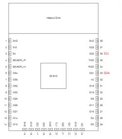
    Problem 2 -> I2c - I switched from Eagle to EasyEd. My project uses the model for ESP32-WROOM-32D in which the pins are labelled like this:

    pin 20 - marked as SCL
    pin 21 - marked as SDA

    In the documentation it is as follows:

    pin 20 - CLK
    pin 21 - SD0

    https://www.espressif.com/sites/default/files...32-wroom-32d_esp32-wroom-32u_datasheet_en.pdf

    On a development board e.g. ESP32 devkit and similar:
    pin 21 - SDA
    pin 22 - SCL

    https://rntlab.com/question/what-pins-are-the-i2c-pins-on-the-esp32/

    I have a bare ESP32-WROOM-32D chip.
    Can someone direct me under which pins I should connect my peripherals: DS3231MZ+, mcp23017 ?
  • Helpful post
    #30 18482607
    khoam
    Level 42  
    czarny8322 wrote:
    In the documentation it is as follows:
    pin 20 - CLK
    pin 21 - SD0
    https://www.espressif.com/sites/default/files...32-wroom-32d_esp32-wroom-32u_datasheet_en.pdf
    .
    This does not apply to I2C and these are not GPIO numbers, but rather the leg numbers of the ESP32-WROOM-32D chip.

    czarny8322 wrote:
    On a development board e.g. ESP32 devkit and similar:
    pin 21 - SDA
    pin 22 - SCL
    .
    Correct, this is the GPIO numbering and the default SDA/SCL assignment to these GPIOs.

    czarny8322 wrote:
    I have a bare ESP32-WROOM-32D chip.
    .
    So on leg #33 of the chip is GPIO 21 (SDA) and on leg #36 is GPIO 22 (SCL).
    ESP32, battery back-up and digital potentiometer amplifier control .

Topic summary

The discussion revolves around building a radio using an ESP32 microcontroller with battery backup and controlling a PAM8403 amplifier via a digital potentiometer (X9C103). Key concerns include the feasibility of the battery backup circuit, voltage compatibility between the ESP32 (3.3V) and the X9C103 (5V), and potential errors in the schematic. Participants highlight the need for logic level conversion, the limitations of using a CR2032 battery for powering the ESP32, and the importance of deep sleep mode for power management. Suggestions include using an external RTC (DS3231MZ+) for timekeeping and exploring alternative power solutions like 18650 batteries. The conversation also touches on issues with I2C connections and resistor specifications in the circuit design.
Summary generated by the language model.
ADVERTISEMENT