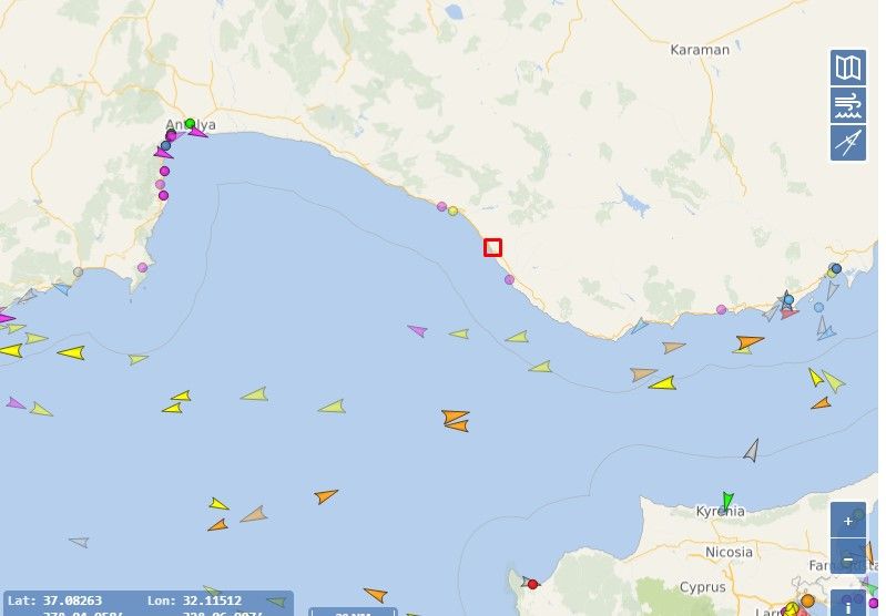
In previous articles I have already mentioned the possibility of receiving interesting parametric information from aircraft, an air-band receiver for listening to conversations between pilots and traffic controllers. No less interesting may be the data on marine vessels, transmitted by the AIS system. There are websites similar to the popular flightradar24 or flightaware, for example MarineTraffic or VesselFinder.
Tracking of aircraft or marine traffic: method of data collection .
The latter use the same method of collecting information and transmitting it to a website, so that any user can check the status of a flight or the voyage of a seagoing vessel. The way it works is that volunteers around the world install a receiver, register it in the system, connect it to the Internet and deliver the data to a server, which processes and shows it in a form that is clear to the user, i.e. as an image on a map.
In this way, when walking along the sea, we can always check what ship we see on the horizon. However, there are situations when we don't have internet, even mobile internet. For example, on our own small sea vessel - a motor or sailing boat - without a suitable device. In such a case, information on maritime traffic can become not only useful, but lives may depend on it.
Another issue - some marine vessel owners, most often wealthy government officials, prohibit the display of data on public services. However, to individual viewers they cannot prohibit it. This is legally and technically impossible.
Anyway, I personally don't own a ship, I have internet almost all the time, but out of curiosity I decided to develop my own Marine AIS receiver.
Characteristics of the project .
Having an SDR receiver of the RTL-SDR type does not even require much programming experience. All you need to do is install the appropriate apps on your smartphone or notebook and that's it. I will describe here step by step for beginners the whole procedure, and at the end of the article I will add a schematic and a description of a fully self-contained receiver that avoids the use of an RTL-SDR dongle.
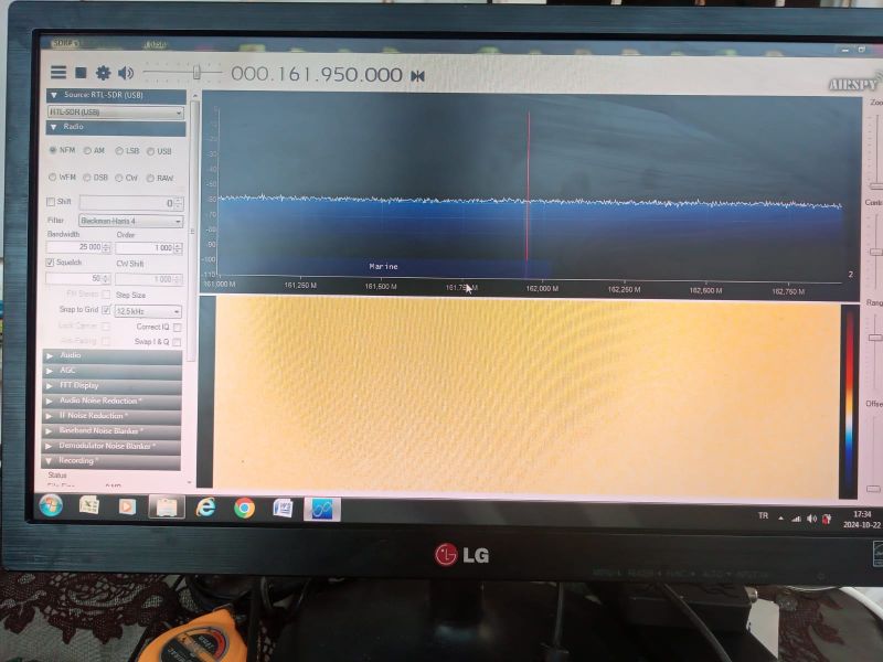
The aim is to pick up the signal transmitted by the transmitter placed on the ship. The data emission takes place at 161.975 MHz or 162.025 MHz with a bandwidth of 25 kHz, with frequency modulation. Connect the RTL-SDR receiver. We start the Sharp SDR programme, set the frequency, band and modulation mode (narrow FM - 25 kHz). With the presence of a marine vessel within the sensitivity range of the antenna-receiver link, we will see something similar and hear the characteristic sound of a digital signal.
.
We decode the received data on the computer using the ShipPlotter software. Unfortunately it costs a little (about 100 zl), but you can play around with it free of charge for 3 weeks. By default, this programme receives the sound signal from an analogue receiver or saved in WAV format from another instrument. In our case, the receiver is the same computer on which this application runs. So we can connect the input/output of the sound card and start receiving data. However, often on laptops we have one plug for input and output, you have to solder on the jack wires. The simplest solution would be to use any program that connects the output to the input in a virtual way. There are plenty of programs for this purpose and anyone can use any.
Personally, when I experiment, I use a physical connection between two computers: one which acts as a receiver and the other as a decoder and data display. It's not a practical solution, but it suits me because I'm going to use a decoder with an analogue receiver, instead of an RTL-SDR dongle, after the experiments.
Anyway, once this hardware-software complex is up and running, in the ShipPlotter application menu we press View - Messenges. If the hardware and software are working correctly, we get data from the ships.
Building and operation .
As for analogue equipment: for several reasons I do not like digital receivers. Especially as in the case with AIS we do not need all their capabilities. I prefer analogue instruments of this type. Especially since in this case the receiver can be very simple.
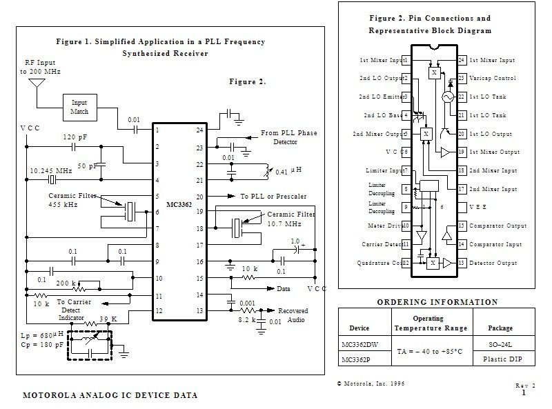
For example, it can be realised on the popular MC3362 integrated circuit. In fact, it is developed by Motorola for narrowband receivers. However, this is achieved by a double frequency conversion. The first (usually 10.7 MHz) is used to attenuate the mirror channel, and by the second (455 kHz) we obtain the narrow bandwidth of the audio signal. To extend it, it is sufficient to dispense with the second transformation and to use a broadband filter (25 kHz) at 10.7 MHz in the first IF.
A typical receiver schematic on the MC3362 looks as follows:
.
Tracking of aircraft or marine traffic: method of data collection .
The latter use the same method of collecting information and transmitting it to a website, so that any user can check the status of a flight or the voyage of a seagoing vessel. The way it works is that volunteers around the world install a receiver, register it in the system, connect it to the Internet and deliver the data to a server, which processes and shows it in a form that is clear to the user, i.e. as an image on a map.
In this way, when walking along the sea, we can always check what ship we see on the horizon. However, there are situations when we don't have internet, even mobile internet. For example, on our own small sea vessel - a motor or sailing boat - without a suitable device. In such a case, information on maritime traffic can become not only useful, but lives may depend on it.
Another issue - some marine vessel owners, most often wealthy government officials, prohibit the display of data on public services. However, to individual viewers they cannot prohibit it. This is legally and technically impossible.
Anyway, I personally don't own a ship, I have internet almost all the time, but out of curiosity I decided to develop my own Marine AIS receiver.
Characteristics of the project .
Having an SDR receiver of the RTL-SDR type does not even require much programming experience. All you need to do is install the appropriate apps on your smartphone or notebook and that's it. I will describe here step by step for beginners the whole procedure, and at the end of the article I will add a schematic and a description of a fully self-contained receiver that avoids the use of an RTL-SDR dongle.
The aim is to pick up the signal transmitted by the transmitter placed on the ship. The data emission takes place at 161.975 MHz or 162.025 MHz with a bandwidth of 25 kHz, with frequency modulation. Connect the RTL-SDR receiver. We start the Sharp SDR programme, set the frequency, band and modulation mode (narrow FM - 25 kHz). With the presence of a marine vessel within the sensitivity range of the antenna-receiver link, we will see something similar and hear the characteristic sound of a digital signal.
.
We decode the received data on the computer using the ShipPlotter software. Unfortunately it costs a little (about 100 zl), but you can play around with it free of charge for 3 weeks. By default, this programme receives the sound signal from an analogue receiver or saved in WAV format from another instrument. In our case, the receiver is the same computer on which this application runs. So we can connect the input/output of the sound card and start receiving data. However, often on laptops we have one plug for input and output, you have to solder on the jack wires. The simplest solution would be to use any program that connects the output to the input in a virtual way. There are plenty of programs for this purpose and anyone can use any.
Personally, when I experiment, I use a physical connection between two computers: one which acts as a receiver and the other as a decoder and data display. It's not a practical solution, but it suits me because I'm going to use a decoder with an analogue receiver, instead of an RTL-SDR dongle, after the experiments.
Anyway, once this hardware-software complex is up and running, in the ShipPlotter application menu we press View - Messenges. If the hardware and software are working correctly, we get data from the ships.
Building and operation .
As for analogue equipment: for several reasons I do not like digital receivers. Especially as in the case with AIS we do not need all their capabilities. I prefer analogue instruments of this type. Especially since in this case the receiver can be very simple.
For example, it can be realised on the popular MC3362 integrated circuit. In fact, it is developed by Motorola for narrowband receivers. However, this is achieved by a double frequency conversion. The first (usually 10.7 MHz) is used to attenuate the mirror channel, and by the second (455 kHz) we obtain the narrow bandwidth of the audio signal. To extend it, it is sufficient to dispense with the second transformation and to use a broadband filter (25 kHz) at 10.7 MHz in the first IF.
A typical receiver schematic on the MC3362 looks as follows:
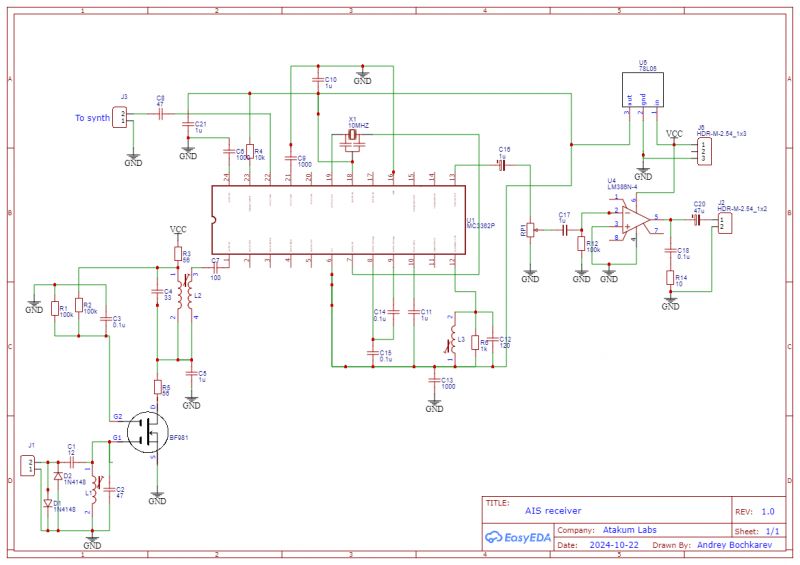
The broadband variant, on the other hand, looks like this:
.
As you can see, the first IF signal from the filter is fed to pin 7, instead of 17. After its amplification, it is detected on the discriminator with inductor L3 and capacitor C12. Obviously, the contour, which consists of these elements, must have the frequency of the first IF. The ceramic filter on 10.7 must have a bandwidth of not less than 25 kHz.
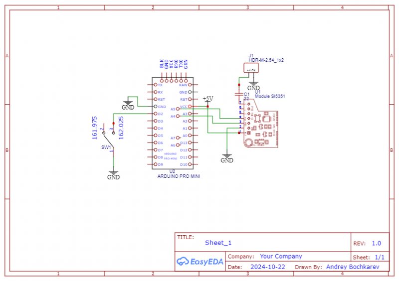
The heterodyne is to be set to one frequency, which is 161.975 - (or +) IF. A simple quartz oscillator or a frequency synthesiser on an Arduino and si5351 IC can be used:
.
The simple code can be found below the spoiler:
Spoiler:
.
#include "si5351.h"
#include "Wire.h"
//----------------------------------------------------------------------------
// LO (heterodyne) frequencies * 10 Hz
const uint32_t chan_tab[10] =
{
15125000,
15132500,
};
Si5351 si5351;
byte channel;
#define SELECT_PIN_1 2
//--------------------------------------------------------------------------------
byte read_chan_number()
{
if (!digitalRead(SELECT_PIN_1)) return 1;
return 0;
}
void set_current_chan()
{
byte new_chan;
new_chan = read_chan_number();
if (channel != new_chan)
{
digitalWrite(LED_BUILTIN,HIGH);
channel = new_chan;
si5351.set_freq(chan_tab[channel] * 10000ULL, SI5351_CLK0);
digitalWrite(LED_BUILTIN,LOW);
}
}
//--------------------------------------------------------------------------
void setup() {
Serial.begin(9600);
bool i2c_found;
pinMode(LED_BUILTIN,OUTPUT);
pinMode(SELECT_PIN_1,INPUT_PULLUP);
i2c_found = si5351.init(SI5351_CRYSTAL_LOAD_8PF, 0, 0);
if(!i2c_found) // si5351 not found
{
while(1)
{
digitalWrite(LED_BUILTIN,HIGH);
delay(200);
digitalWrite(LED_BUILTIN,LOW);
delay(100);
}
}
channel = 255;
si5351.update_status();
si5351.drive_strength(SI5351_CLK0, SI5351_DRIVE_2MA);
si5351.set_correction(81000, SI5351_PLL_INPUT_XO);
set_current_chan();
si5351.output_enable(SI5351_CLK0, 1);
}
void loop()
{
set_current_chan();
Serial.println("channel" + String (channel));
delay(100);
}
Antenna selection .
An important consideration for this system is the antenna. Common and cheap RTL-SDR receivers are sold with one that is not suitable for anything. It looks like a 500-1000 MHz frequency. AIS reception needs a more efficient solution. In the case with a marine vessel installation, this can be a GP (Ground Plane) type antenna, having omnidirectional radiation in the horizontal plane. It consists of one vertical radiator of length λ/4 (λ as we know is the wavelength, in our case it is about 1.6 m) and several counterweights of length not less than λ/4. The counterweight can be a flat metal roof. When we use the receiver in stationary conditions, i.e. on the shore, it makes sense to use a directional antenna, "looking" towards the sea.
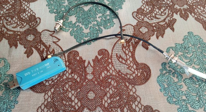
My GP antenna is located on the roof of an apartment building. It is connected to the receiver with a coaxial cable (as in satellite TV) via an MCX-F-type adapter.
.
Cool? Ranking DIY


