Hi,
I have a module that consists of two boards - one board contains the procec (ESP32), expanders, 230VAC / 5 VDC inverter (IRM-10-5), 3.3V stabiliser and the other is a board with LEDs, 4x20 LCD and microswitches.
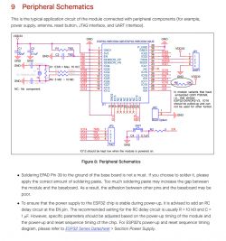
Overall, this is the third version of the prototype, the previous two worked without problems, while in this version I have a problem in that after powering up the module does not start - the display backlight is on and the ESP is as if in a reset state - no inputs and outputs work. However, when the RESET button is pressed, the ESP32 starts up and the module works as it should.
I should add that I've already tried powering the device from a lab power supply, but it doesn't change anything - when powered, the ESP32 doesn't boot.
But powering the ESP from the USB, the whole thing starts right up.
I have no idea where the problem is anymore - I thought it was an inverter issue, but it looks like not.
Please help.
 .
.
I have a module that consists of two boards - one board contains the procec (ESP32), expanders, 230VAC / 5 VDC inverter (IRM-10-5), 3.3V stabiliser and the other is a board with LEDs, 4x20 LCD and microswitches.
Overall, this is the third version of the prototype, the previous two worked without problems, while in this version I have a problem in that after powering up the module does not start - the display backlight is on and the ESP is as if in a reset state - no inputs and outputs work. However, when the RESET button is pressed, the ESP32 starts up and the module works as it should.
I should add that I've already tried powering the device from a lab power supply, but it doesn't change anything - when powered, the ESP32 doesn't boot.
But powering the ESP from the USB, the whole thing starts right up.
I have no idea where the problem is anymore - I thought it was an inverter issue, but it looks like not.
Please help.
 .
.


