logo elektroda
logo elektroda
X
logo elektroda

ESP32-C2 Boot Loop After Flashing OpenESP32C2_1.18.158_2M on 2MB WiFi Module

jmkrzyszt 702 21
ADVERTISEMENT
  • #1 21643283
    jmkrzyszt
    Level 6  
    Hello,

    I'm trying to reflash a WiFi module of a solar charging controller with an open source firmware.
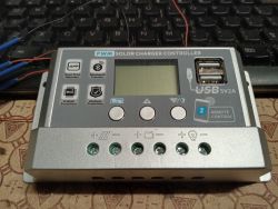
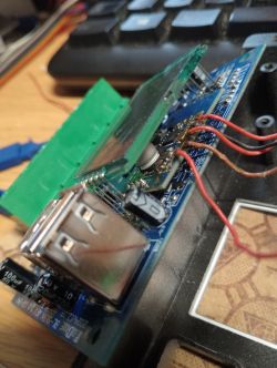
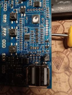
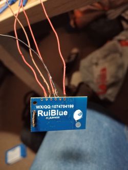
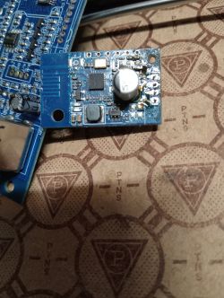
    PWM solar charge controller with LCD screen and dual USB ports on desk Close-up of a BL-SM214R board with attached wires and USB-A socket Close-up of a PCB with tactile buttons, SMD components, and dual USB Type-A port RuiBlue AH_BL8BW005 WiFi module with attached wires ESP32-C2 Wi-Fi module on blue PCB with visible capacitors and SMD components

    Esptool reports:
    Code: Text
    Log in, to see the code

    Flashing the module with:
    Code: Bash
    Log in, to see the code
    succeeds, but then the device (still powered only from my USB-serial adapter) doesn't boot, only reboots spontaneously, e.g.:
    Code: Text
    Log in, to see the code
    I think it also doesn't boot when powered from a car battery since its AP doesn't appear.

    I've also tried tasmota and esphome, with similar results. Reflashed back with original firmware, the device works correctly.

    Any ideas on what I'm doing wrong?
    AI: Could you provide the exact brand and model of the WiFi module and the solar charging controller it's from? This will help determine if there are any known compatibility issues or special requirements for your hardware.
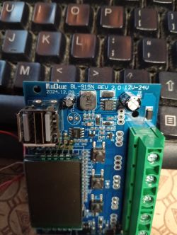
    BL-915N REV 2.0 module with USB port and screw terminal against keyboard background
    https://aliexpress.com/item/1005008843512568.html
    AI: Where did you obtain the OpenESP32C2_1.18.158_2M.factory.bin (and the Tasmota/ESPHome images) you flashed—were they downloaded pre-built, or did you build them yourself? If built, which board or configuration did you select?
    https://github.com/openshwprojects/OpenBK7231.../1.18.158/OpenESP32C2_1.18.158_2M.factory.bin

    Tasmota images marked ESP32C2 available on https://tasmota.github.io/install/

    ESPHome custom image generated with the following configuration (wifi and dependent sections either enabled or disabled):
    Code: YAML
    Log in, to see the code
  • ADVERTISEMENT
  • #2 21643289
    p.kaczmarek2
    Moderator Smart Home
    Can you provide original backup of the firmware?

    @divadiow @insmod ideas? I am not sure if I have C2 at hand, but I am sure that I tested OpenESP32 on S3 just few days ago and it worked well.
    Helpful post? Buy me a coffee.
  • #4 21643315
    p.kaczmarek2
    Moderator Smart Home
    User says he also tried Tasmota, etc, so possibly there is something else wrong than our binary.
    Helpful post? Buy me a coffee.
  • ADVERTISEMENT
  • #6 21643332
    jmkrzyszt
    Level 6  
    >>21643289
    Yes, I'll do, as soon as I capture another copy with my local settings cleared after reflashing.

    Added after 52 [minutes]:

    Unfortunately, my only USB-serial adapter (FTD) suddenly stopped working -- it no longer appears in the system when connected. Since I successfully reflashed original firmware on the problematic module a few times with that adapter, I don't think it could be responsible for my issues with your and other firmware, but anyway, it looks like I need to purchase a new one before I'm able to continue.
  • Helpful post
    #7 21643461
    insmod
    Level 29  
    40Mhz crystal frequency - needs special compile-time flags
    CONFIG_XTAL_FREQ_40=y
    CONFIG_XTAL_FREQ=40

    Added after 1 [hours] 34 [minutes]:

    For lower size binary in esphome
    
        sdkconfig_options:
          CONFIG_COMPILER_OPTIMIZATION_SIZE: y
          CONFIG_COMPILER_OPTIMIZATION_ASSERTIONS_SILENT: y
          CONFIG_COMPILER_OPTIMIZATION_LEVEL_RELEASE: y
          CONFIG_ESP_WIFI_ENTERPRISE_SUPPORT: n
          CONFIG_NEWLIB_NANO_FORMAT: y
          CONFIG_ESP_SYSTEM_PANIC_SILENT_REBOOT: y
          CONFIG_XTAL_FREQ_40: y
          CONFIG_HAL_ASSERTION_SILENT: y
          CONFIG_HAL_LOG_LEVEL_ERROR: y
          CONFIG_ESP_WIFI_ENABLE_WPA3_OWE_STA: n
          CONFIG_VFS_SUPPORT_IO: n
    

    But i see that you have only UART wired out on the module.
    So there is probably some custom UART protocol - you would need to sniff it manually with original firmware.
  • #8 21643665
    jmkrzyszt
    Level 6  
    insmod wrote:
    But i see that you have only UART wired out on the module.
    So there is probably some custom UART protocol - you would need to sniff it manually with original firmware.

    Yes, only UART. My plan is to verify if Modbus protocol is in use.
  • #9 21643673
    p.kaczmarek2
    Moderator Smart Home
    I can help with reverse engineering and writing driver for that in OBK. Start with packets capture.
    Helpful post? Buy me a coffee.
  • ADVERTISEMENT
  • #10 21645590
    jmkrzyszt
    Level 6  
    OK, I received my new USB-serial adapter so I can continue with my attempts.

    First I tried the proposed ESPHome configuration tweaks but that didn't help.  It looks like if 2nd stage boot loader didn't work.  I'm wondering if maybe there is something wrong with partition layout.

    Then I successfully re-flashed the device with original firmware.  Here is a boot log:
    Code: Text
    Log in, to see the code
    The last three lines are then repeated continuously.  Those look to me like Modbus messages.

    There is no response from the solar charger because only the WiFi module is powered up from the USB-serial adapter regulator.  There is also no WiFi connection established, probably because of the missing response.  Tomorrow I'm going to connect the device to a car battery and try to capture Modbus responses from the charger, hopefully reported to the serial console.  Then I'll clean up my WiFi credentials and dump the firmware for sharing.
  • #11 21645598
    p.kaczmarek2
    Moderator Smart Home
    I know modbus well and I've been planning to add it to OBK, this might be a good time to do it.
    useful tool: https://npulse.net/en/online-modbus
    Helpful post? Buy me a coffee.
  • #12 21646385
    jmkrzyszt
    Level 6  
    I'm attaching a serial console log filtered with focus on Modbus data exchange with the solar charge controller over UART.

    In short, two sets of holding registers are queried for their content every 10 seconds:
    Code: Text
    Log in, to see the code
    From time to time, another single register is written with either 0 or 1 value, e.g.:
    Code: Text
    Log in, to see the code

    I haven't been able to clean up all copies of my WiFi credentials stored in the WiFi module flash (there are a couple of them). I can binary edit the firmware dump but then I'm not sure if it will still boot due to potentially invalid checksums. Will the image prepared that way still be useful for you?
  • #13 21647272
    jmkrzyszt
    Level 6  
    I think I found a way to wipe my credentials: overwrite them with dummy data. Partial success so far, but I'll keep going.
  • #14 21647286
    p.kaczmarek2
    Moderator Smart Home
    Hmmm I see that situation has changed. We are now certain that a modbus support is needed. I think I don't really need a copy of your device firmware. I can prepare modbus support in OBK for you. Can you make a list of modbus registers for this specific device and how are they used? Also, maybe a full capture of communication (if that's not present in your previous post?)?

    You know, I can run OBK on Windows - with OBK simulator - so I can easily develop modbus driver for that, especially with your packet capture.

    ESP32 here is a modbus master, right?
    Helpful post? Buy me a coffee.
  • #15 21647346
    jmkrzyszt
    Level 6  
    Yes, ESP32 is a modbus master.

    As I reported, two ranges of holding registers are queried.  Here is what the modbus application from the link you provided tells us about those queries.

    1st range query:
    Code: Text
    Log in, to see the code
    Example response:
    Code: Text
    Log in, to see the code

    2nd range query:
    Code: Text
    Log in, to see the code
    Example response:
    Code: Text
    Log in, to see the code

    In order to find correlations between those registers and physical values measured or controlled by the solar charger, a way of watching values reported over modbus, more convenient than watching console log, would be helpful.  Maybe you could extend the Web Application with fields providing values read from modbus registers at user specified addresses?

    Other than that, I'm still not able to boot OBK (nor any firmware other than factory) on the module, so for now I have no way to test your work.
  • #16 21650678
    jmkrzyszt
    Level 6  
    I've finally resolved the issue of not being able to clean up WiFi credentials from flash with factory firmware. I've erased a flash region that contained multiple copies of those credentials with esptool. After power cycle the module has started correctly, with no WiFi connection. Then I've dumped the flash content, this time with no WiFi credentials.
    Please find a copy attached.

    Modbus communication seems not affected by the flash region erase operation.

    No progress with booting the module with OBK nor other open source firmware.
  • #17 21651602
    divadiow
    Level 36  
    cool. boots for me on 26Mhz C2

    Code: Text
    Log in, to see the code
  • #18 21651654
    jmkrzyszt
    Level 6  
    Other than Crystal frequency: 40MHz vs 26MHz you mentioned, I can see the following other hardware differences when comparing factory firmware boot logs:
    - chip revision: v1.2 vs v1.0
    - SPI Speed: 30MHz vs. 60MHz
    - SPI Flash Size: 2MB vs. 4MB

    I can also see SPI Speed: 60MHz reported by ESP-IDF v5.5 2nd stage bootloader when booting OBK on my device (vs 30MHz reported by v5.0.1 with factory firmware).

    One more hardware difference:
    - detected chipset: generic vs gd
  • #19 21652748
    jmkrzyszt
    Level 6  
    I think I've identified some registers. The range starting at register offset 0x1 seems to provides live values, while the other one starting at register offset 0x1001 is where settings are stored.

    Live values at offset 0x1:
    Code: Text
    Log in, to see the code

    Settings at offset 0x1001:
    Code: Text
    Log in, to see the code
  • #20 21654517
    jmkrzyszt
    Level 6  
    Hello,
    I've managed to boot ESPHome on my ESP32-C2 module with factory installed 2nd stage bootloader. I installed my ESPHome .ota.bin image with esptool at flash address 0x10000. My ESPHome .factory.bin image was just missing the 2nd stage bootloader code, replaced with all ones (0xff). That's an issue with ESP32-C2 support in the current ESPHome, I believe (I tried 2025.8.1 and 2025.8.2). Then, I'm not able to use OTA for firmware updates for now, but anyway, I can continue with exploring the device.  BTW, thank you @insmod for sharing your ESPHome configuration hints, those occurred quite helpful.  Here is the boot log.
    Code: Text
    Log in, to see the code

    EDIT:
    OTA is possible, for it to work one needs to locate a partitions.bin file for the device in the esphome runtime file tree and upload it to the flash over serial with esptool at offset 0x8000.

    I also tried a similar trick with OBK .img but that didn't work. However, boot log looked different than when OBK .factory.bin was installed, maybe it can shed more light on why boot fails. Here is a copy:
    Code: Text
    Log in, to see the code

    For completeness of the record, I've also tried booting ESPHome with OBK 2nd stage bootloader, and that does't work either.
    Code: Text
    Log in, to see the code
  • #21 21655766
    jmkrzyszt
    Level 6  
    ESPHome configuration of Modbus UART:
    Code: YAML
    Log in, to see the code

    Other than that, there are two LEDs, rather not visible from outside of the device enclosure.
    Code: YAML
    Log in, to see the code
  • ADVERTISEMENT
  • #22 21687716
    jmkrzyszt
    Level 6  
    Hi @p.kaczmarek2, while I've already set up my device with ESPHome and connected it to my HA setup where I'm now monitoring my solar charger, I'm still willing to test an OBK based solution once you have Modbus support ready for testing and OBK can boot on my device.

Topic summary

An ESP32-C2 WiFi module from a solar charging controller with 2MB flash memory was reflashed using OpenESP32C2_1.18.158_2M firmware but entered a boot loop. Esptool confirmed the chip as ESP32-C2 (revision v1.2) with a 40MHz crystal frequency and 2MB flash size (Manufacturer: a1, Device: 4015). Attempts to flash alternative firmware such as Tasmota also failed, suggesting issues beyond the binary itself. Discussion highlighted the need for specific compile-time flags for 40MHz crystal frequency (e.g., CONFIG_XTAL_FREQ_40=y) and noted that only UART is wired out on the module, implying a custom UART protocol might be in use, possibly Modbus. Testing on ESP32-C3 and ESP32-C6 modules with similar firmware was successful, indicating the problem may be specific to the ESP32-C2 or the module’s hardware setup. The original firmware backup is requested for protocol analysis. The user’s USB-serial adapter (FTDI) malfunctioned, temporarily halting further testing.
Summary generated by the language model.
ADVERTISEMENT