Good morning,
I have a problem integrating a Zigbee module with a Simon 55 illuminated switch.
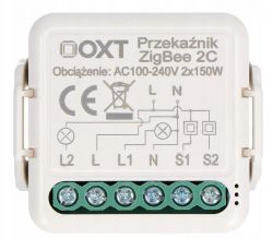
I have 2 different Zigbee modules from the light switches - an OXT and a straight from China GIRIER Tuya ZigBee 3.0 - externally, to be honest, they look identical.
When I had the connectors themselves fitted to the bulb - everything worked as expected.
When I connected the Zigbee module - I could only control the on/off via the Tuya app. The physical button didn't change state, as if it was still on.
I went to my senses and measured the voltages with a meter. It turned out that the illuminated switch in the on position was giving an alternating voltage of 230 volts, but in the off position it was still generating a voltage of about 66 volts. The bulb did not light up, but when I changed the light source to a GU9 LED attached to the lamp I bought, it turned out that on the switch alone (without the smarthome module) in the on position the bulb shines brightly, in the off position much less, but still. I should add that the Zigbee modules claimed to be compatible with 110-230 volts, but yet when 66 volts was applied it still saw an 'ON' state.
Do you know of any solution to the problem?
- another Zigbee module
- solder something in the circuit to reduce the voltage when in the off state, but so that the backlight in the physical button still works?
Regarding the connection - according to the attached file


