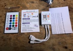
The OP-WF-A3 is a three-channel RGB LED colour strip controller offering control in two ways - via Wi-Fi from the Tuya app, or via the included remote control. Here I'll show the inside of it, then I'll change its software so that it can be programmed a bit like an Arduino, and finally I'll show the decoding of the remote control codes and their handling in the new firmware.
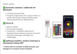
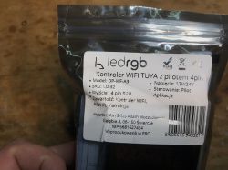
We bought the kit for £50 - it doesn't include the tape and power supply. The controller works with RGB tape from the factory, but after my modification it will be freely configurable - it will be able, for example, to handle also CCT tape (white temperatures) or several separate white tapes.
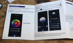
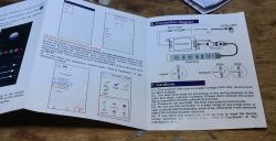
I do not discuss the Tuya application, I only include a photo of the instructions below:


Interior of OP-WF-A3
Lift the cover, it's on a latch. There are no screws.
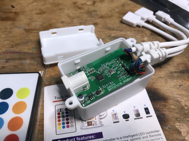
PCB designation: 240315 (date? 15 03 2024?) BK7231 RGBWY V0.1.
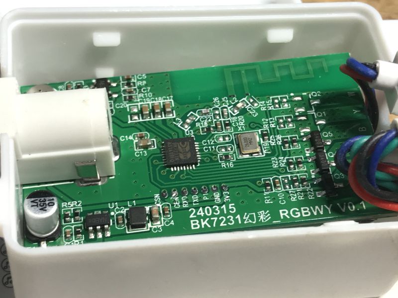
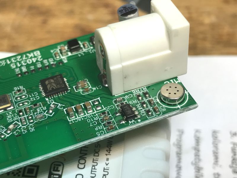
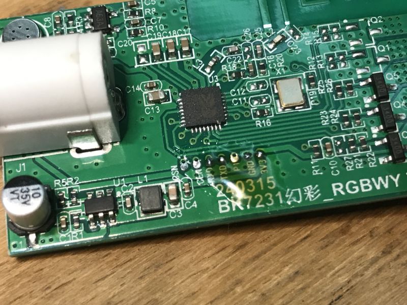
BK7231N is directly on the PCB. There is no separate Wi-Fi module. The antenna from the Wi-Fi is also in the form of a track on the PCB. In the power section there is an inverter to reduce the voltage. There is room for 5 transistors on the board, so theoretically there could be an RGB + CCT strip, but only 3 of them are manned. Next to the circuit there are signals for programming it on the pads.
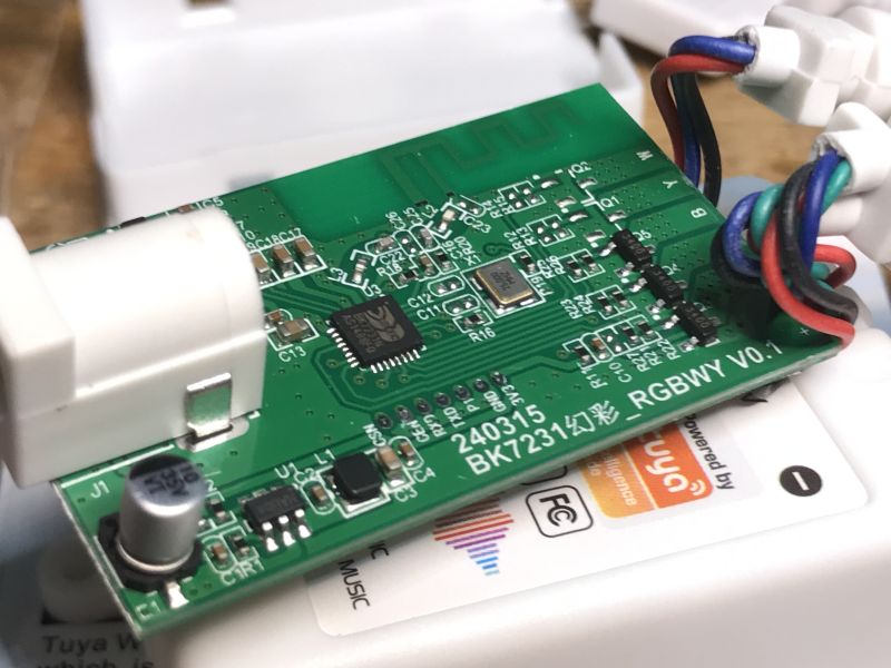
On the other side we still have the microphone with amplifier:
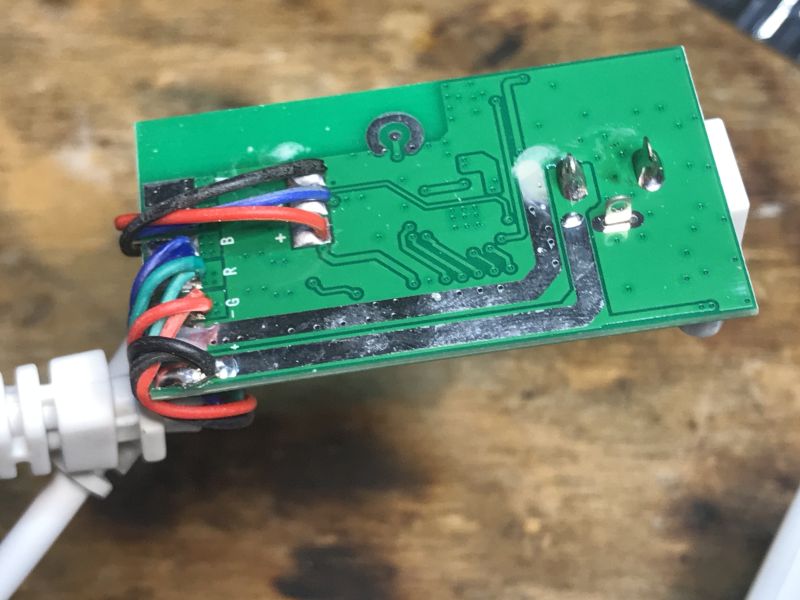
Still left is the underside of the PCB - the tracks for the higher current are thickened and tinned:
Programming OP-WF-A3
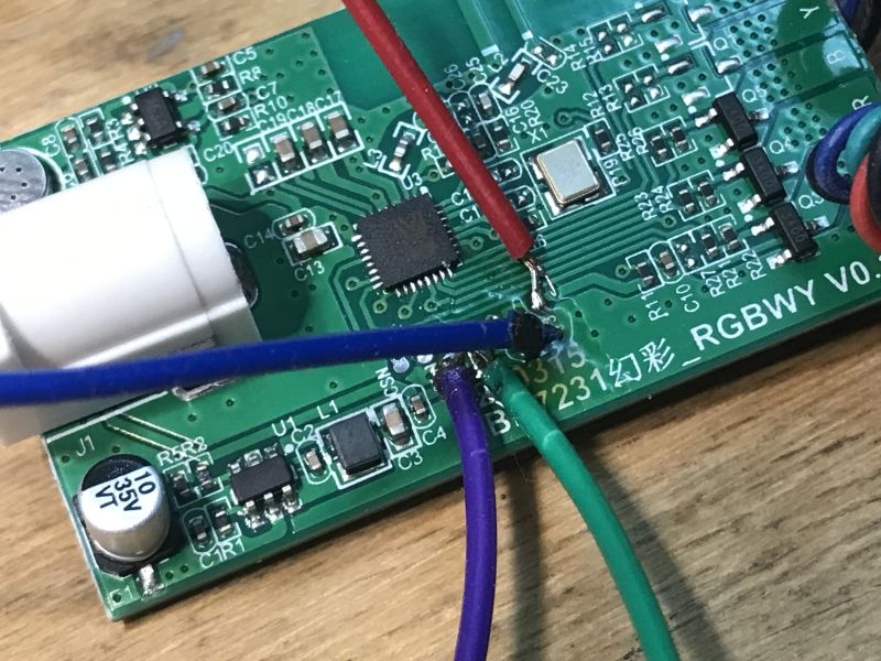
You will need a USB to UART converter. Here we have everything outputted to the pads. These need to be whittled down first:
Then we solder the wires:
We upload the OBK:
https://github.com/openshwprojects/OpenBK7231T_App
We follow the instructions of our flasher:
https://github.com/openshwprojects/BK7231GUIFlashTool
Backup:
https://github.com/openshwprojects/FlashDumps/commit/7c149aba30cc6e96e1b15167d2965c8de83cf81f
The flasher should also detect the GPIO configuration, although this did not work out for this device.
Code: JSON
Configuration of the OP-WF-A3
The PWM pins can be found using GPIO Doctor:
GPIODoctor in OpenBeken - a convenient way to learn about GPIO roles in an IoT device
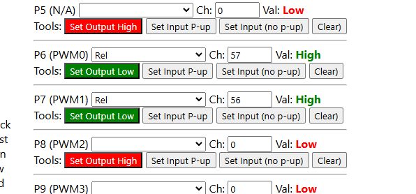
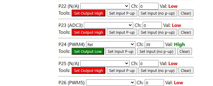
You have to trace the path to the IR receiver yourself - but I have already done that for you, it is on pin P26:
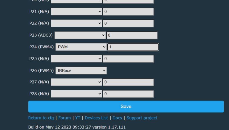
We have to manually examine the IR signals - we restart the device after setting the IRRecv role and look in the log. We point the remote at the receiver and press the buttons. We look at what is being received.
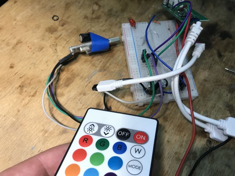
On and off button:
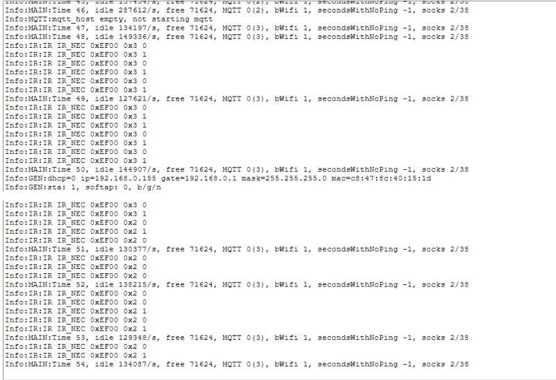
The buttons are NEC standard. Codes 0x02 and 0x03 are responsible for switching on/off.
Similarly, the brightness control:
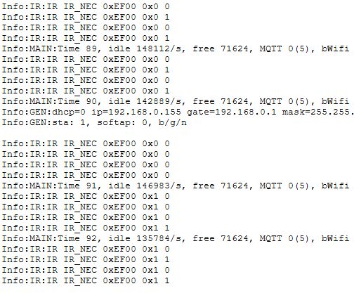
In this way, we learn their codes and can then match OBK commands to them, as for example in the material on the BK7238:
Tutorial/presentation on the operation of the NiceMCU BK7238/T1 IR remote control - Home Assistant
You can still add buttons on their own to 'physically' control the LEDs - for me this is essential:
A controller programmed in this way is compatible with Home Assistant:
The converted strips can also be combined into DGR groups in this way:
Summary
This was a very simple product to convert. Just solder the cables, the pads are given as if on the palm of your hand. Upload the firmware and you gain new possibilities - you can freely script the buttons of the remote control, as well as add additional physical buttons and even additional sensors such as DHT11 or DS18B20. All this is, of course, compatible with Home Assistant. Such a converted product also works 100% locally, of course, without the manufacturer's cloud and poses a risk to user privacy.
And which LED strip controllers do you use?
Cool? Ranking DIY Helpful post? Buy me a coffee.


