logo elektroda
logo elektroda
X
logo elektroda

ESP32 WTH01 - how to plan the connection of modules to the ESP

sznickers 75 5
ADVERTISEMENT
Treść została przetłumaczona polish » english Zobacz oryginalną wersję tematu
  • #1 21761663
    sznickers
    Level 11  
    Hello,
    i would like some feedback, I want to connect some modules to my ESP32WTH01 board, the question is where is the best place to connect these modules to make them work together properly?
    I have free GPIOs on the board marked in red in the picture. RX and TX are out of the question as I use them for PZEM004T.
    All these modules work over I2C, so the question is whether GPIO-4 and GPIO-14 will be ok ? BO this is how I have connected them for the moment.
    The MCP23017 module supposedly has both inputs and outputs. I am currently using it for relays- I have connected it to the ESP board and relays to it. Is it possible to connect e.g. ds18b20 as input to this module ?
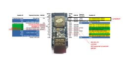
    ESP32WTH01 board with highlighted available GPIO pins in red on schematic
    ESP32 WTH01 - how to plan the connection of modules to the ESP
    ESP32 WTH01 - how to plan the connection of modules to the ESP
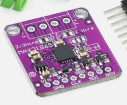
    Purple MAX31865 module with labeled pins: VIN, 3V3, GND, CLK, SDI, SDO, CS, RDY
  • ADVERTISEMENT
  • #2 21761682
    inot
    Level 38  
    sznickers wrote:
    Is it possible to connect e.g. ds18b20 as input to this module ?
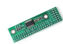
    Of course it is possible, only that in this case you cannot use the ready-made DS18B20 library.
  • ADVERTISEMENT
  • #3 21761699
    sznickers
    Level 11  
    I use ESP Easy in the will to explain. I call the relays connected via the MCP expander with a command e.g. MCPGPIO,1,0.
    When I add a new device e.g. DS18B20 in the pin drop-down list there are only GPIOs and no MCPGPIOs - those from the expander, well unless it is to write a rule.
  • ADVERTISEMENT
  • #4 21761708
    inot
    Level 38  
    Unfortunately, when it comes to the subject of ESP Easy, it's not my 'field'.
  • ADVERTISEMENT
  • #5 21761721
    sznickers
    Level 11  
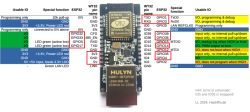
    This is how I wired it, this is how it works at the moment - 43% is occupied on the board.
    ESP32 WT32 pinout diagram with labeled GPIO usage for sensors and I2C devices
    The question is whether I have chosen the right pins, or whether something could possibly be changed.

    Added after 13 [minutes]:

    >>21761708
    I understand.
    Maybe I need to add a Switch input device MCP23017- I haven't tried that yet
    https://espeasy.readthedocs.io/en/latest/Plugin/P009.html
    This is a secondary issue for me, but it is also bothering me.
  • Helpful post
    #6 21761749
    khoam
    Level 42  
    sznickers wrote:
    When I add a new device e.g. DS18B20 in the pin dropdown list there are only GPIOs and no MCPGPIOs - those from the expander, well unless it is to write some rule.

    The I/O lines of the MCP23017 are not capable of handling or correctly interpreting the 1-Wire protocol. Regardless of what firmware is used on the ESP32. The DS18B20 should be connected directly to one of the GPIOs. There are indeed 1-Wire to I²C bridges such as the DS2482/DS2484, but the price is a bit daunting.

    sznickers wrote:
    Question if I have chosen pins well, or if something could possibly be changed.

    In my opinion, the "safest" GPIOs for connecting the DS18B20 are GPIO13, GPIO16, GPIO17, GPIO18, GPIO19, GPIO21, GPIO22, GPIO23, GPIO25, GPIO26, GPIO27, GPIO32, GPIO33.
ADVERTISEMENT