logo elektroda
logo elektroda
X
logo elektroda

Missing SMD component on ADC/NTC lines - COSORI Dual Blaze CAF-P583S-KEU (E01 error)

ardi_ma 363 2
ADVERTISEMENT
  • Need pad dimensions to identify missing SMD parts

    #1 21941819
    ardi_ma
    Level 2  
    Posts: 2
    Missing SMD component on ADC/NTC lines - COSORI Dual Blaze CAF-P583S-KEU (E01 error) Missing SMD component on ADC/NTC lines - COSORI Dual Blaze CAF-P583S-KEU (E01 error) Missing SMD component on ADC/NTC lines - COSORI Dual Blaze CAF-P583S-KEU (E01 error) Missing SMD component on ADC/NTC lines - COSORI Dual Blaze CAF-P583S-KEU (E01 error)

    Hi everyone,

    I'm trying to repair a COSORI Dual Blaze Air Fryer (CAF-P583S-KEU) that shows an E01 error (temperature sensor open circuit).

    **Root cause found:**
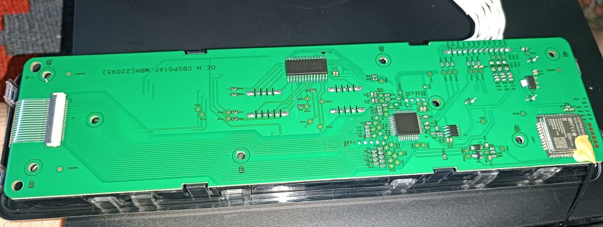
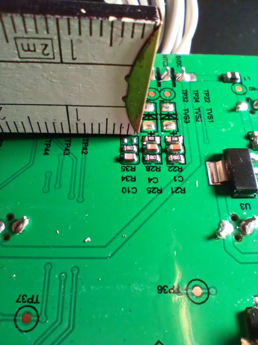
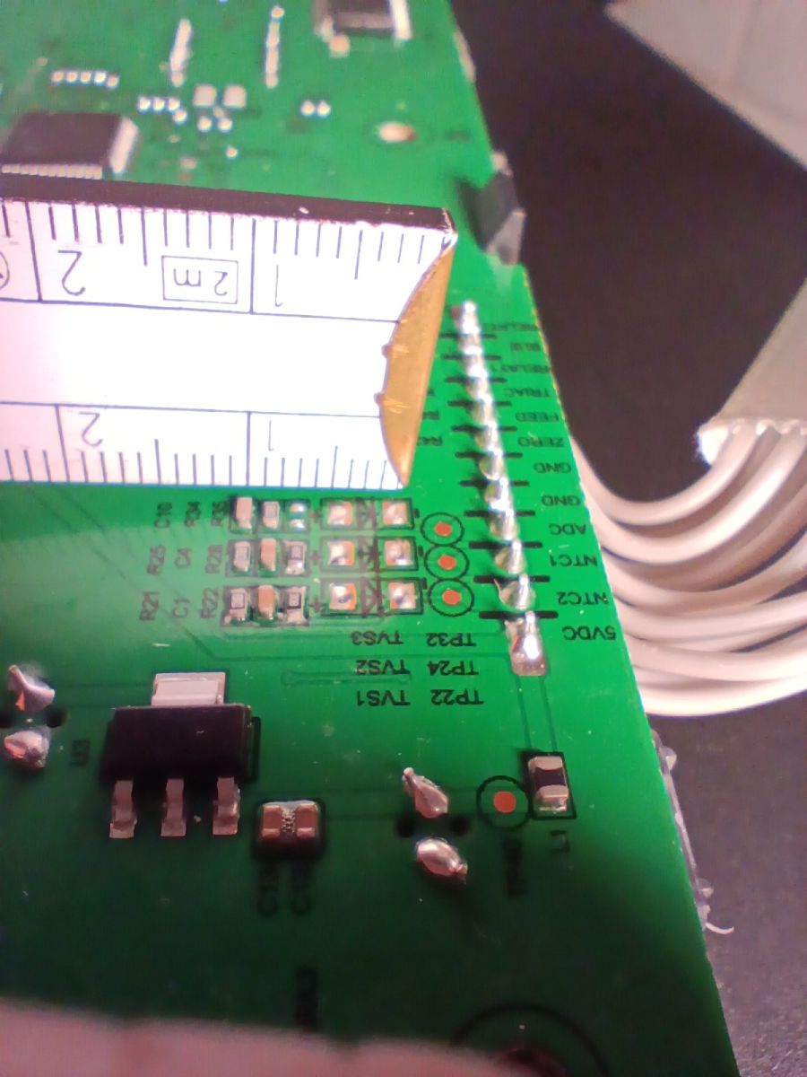
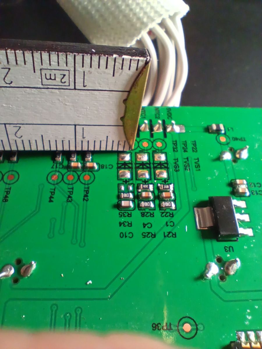
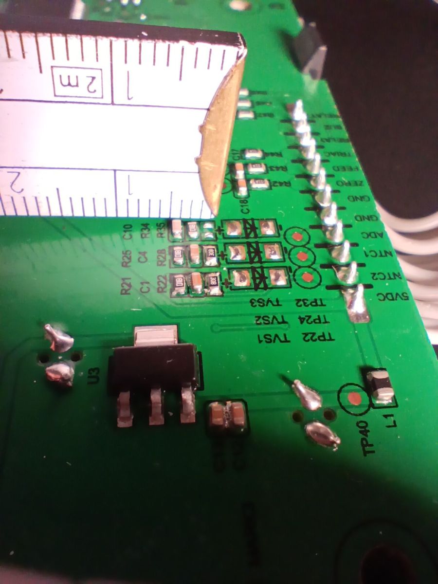
    Upon inspecting the control board (SP01AF-C-V2.1P2.1), I discovered a missing SMD component on the ADC/NTC lines. The NTC1 and NTC2 lines each have a component marked "30B" in the same position, but the ADC line is missing this component and also I guess 3 diodes (TVS - transient-voltage-suppression) entirely.

    **My questions:**
    1. What does the code "30B" represent in SMD marking? Is it 3.0Ω or 30Ω?
    2. What package size is likely used here (0402 or 0603 or something else)?
    3. How about the TVS diodes?

    I have attached close-up photos of the board showing the missing components location.

    Thank you in advance for any help!
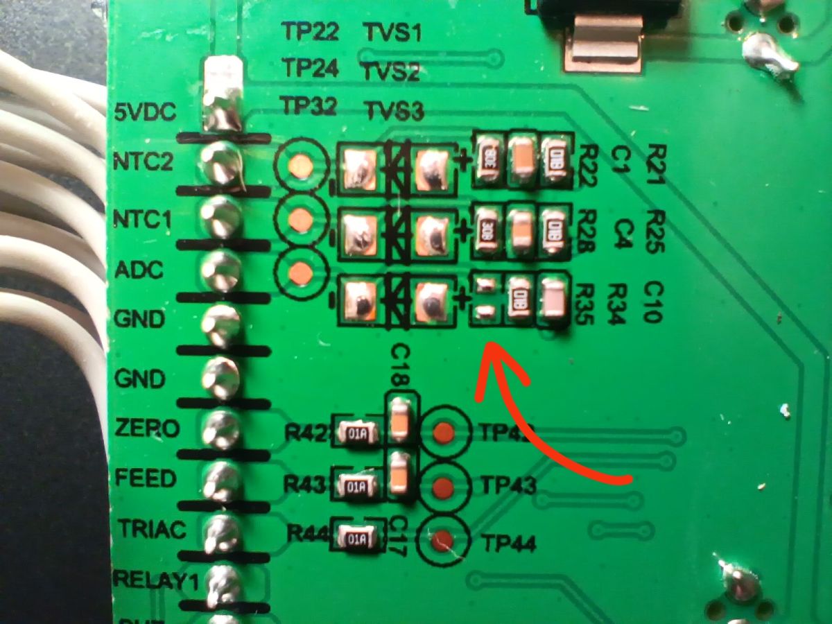
    Close-up of a green PCB with SMD parts and a red curved arrow pointing to a component area Green PCB with ICs and connectors mounted in a black device housing

    AI: Can you measure the resistance/continuity of the existing “30B” components on NTC1 and NTC2, preferably at least in-circuit, and share the values?
    2 kOhm
    AI: Can you provide the physical dimensions of the “30B” component pads and the missing TVS diode pads, or a close-up photo with a ruler/caliper for scale?
    The photos are attached.
  • ADVERTISEMENT
  • 2 kΩ EIA-96 resistor identified as 30B

    #2 21943054
    maks1239
    Level 6  
    Posts: 12
    The resistor marked 30B has a value of 2 kΩ; it is colour-coded according to the EIA-96 system.
    I don’t know anything about the rest, but I don’t think the fault is caused by these missing components. There are no signs of burnout, nor does it look as though anyone has tampered with it to remove them. Manufacturers often produce a single circuit board for several versions of a device and leave empty spaces.
  • NTC lines near zero suggest sensor path fault

    #3 21943378
    ardi_ma
    Level 2  
    Posts: 2
    >>21943054

    Thank you for your response and for identifying the resistor value.

    Regarding the missing component being DNP - that makes sense. However, I have some voltage measurements that I think are more relevant to the fault:

    **Measurements taken while the device is powered on (showing E01):**
    - 5 VDC rail: 4.99 V ✓ (normal)
    - ADC line: 4.31 V (abnormally high, I guess)
    - NTC1 line: ~47 mV (nearly zero)
    - NTC2 line: ~48 mV (nearly zero)

    **What I would expect:**
    With healthy NTC sensors (~200 kΩ at room temperature) and a 5 V supply, the NTC lines should show somewhere between 1-3 V depending on the voltage divider resistors. Instead, they show nearly zero.

    If I do not mistake, the ADC line showing 4.31 V (close to 5 V) suggests the microcontroller is seeing no sensor signal at all - as if the sensors are disconnected.

    **Hardware already verified as good:**
    - Both NTC sensors: ~200 kΩ ✓
    - CN1/CN2 connectors: secure ✓
    - All thermal fuses: continuity ✓
    - Main fuse F1 (T2A/250V): intact ✓
    - Firmware: updated via VeSync app ✓

    Could the nearly-zero voltage on NTC1/NTC2 lines point to a specific component failure? Any guidance would be greatly appreciated.
ADVERTISEMENT